Pavel be assured that I don’t find your response as harsh. It’s all technical, not personal. And I respect your work and your contribution here.
This is what I want to convey too. ‘Current flow seeks path of least Impedance - not just Resistance’
Furthermore, the impedance of this loop will vary with frequency.
http://www.analog.com/static/imported-files/application_notes/6001142869552014948960492698455131755584673020828AN_345.pdf
George
If a wire finds a nearby return path the inductance will decrease not increase.
This is what I want to convey too. ‘Current flow seeks path of least Impedance - not just Resistance’
Furthermore, the impedance of this loop will vary with frequency.
http://www.analog.com/static/imported-files/application_notes/6001142869552014948960492698455131755584673020828AN_345.pdf
George
Here he talkes about the influence of the resistance and capacitance but in my book it solves the problem of inductance too .... at a price... the -6dB voltage devider at audio frequencies.
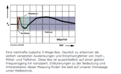
Audio Buffer in english
Audio Buffer in english
Thanks for kind words, Joachim. Yes, it helps to minimize influence of cable properties and it minimizes interferences as well. Again, it is a non-standard solution (series and terminating resistors matched to cable used, terminating resistor itself), so it will not be commercially accepted.
Last edited:
Revel speakers past the Toole test just fine. Are they the best speakers in the world ?
For example, having a L/R4 crossover they distort step response gross.
They probably sound "nice."
Toole's tests are not only ones.
Would they pass Tom Danley's generations test? That is, play some music thru the speakers, record it, then play the recording thru the speakers, then record that and play it, then record that and play it, etc. Do it outdoors so there's no room acoustics interference. How many generations before the sound is degraded compared to the original playback? Mic doesn't hear what humans hear - flaws will be magnified and experimenter becomes sensitized to deficiencies/inaccuracies.
That recording test is known ( Quad , Wharfedale, Cabasse ) but not used any more nowadays.
I think that electronics are more " perfect " than the loudspeaker-room interface.
Of cause there is still the probem of recording.
Conversion processes make trouble, converting air movement into electrical and then back the other way.
I think that electronics are more " perfect " than the loudspeaker-room interface.
Of cause there is still the probem of recording.
Conversion processes make trouble, converting air movement into electrical and then back the other way.
Last edited:
Your schematic has two inputs, with the 47 ohm/cap combo apparently tied to chassis at the input connector. So you have tied to ground in at least two places. In addition, you have placed the outputs close to the inputs, you have an output loop which can broadcast to the input loop. Yes, you do have the output wires organized to try to reduce loop, but the physical spacing of the output posts does limit you.Once again, the photo provided is the final product (with balanced inputs), but today I have measured a prototype that has SE inputs (I have no final product available). These SE inputs have bodies tight to chassis through C//R. The final version has balanced input with XLR's (both) directly on chassis.
Yet, your test diagram does not continue the loop formed by the IC's, you terminate one input with a resistor. That unfortunately, is not a valid test of in-situ crosstalk, as it does not place the amp into the situation which will exist at the customer.
Unfortunately, it is impossible to explain to the piece of wire (regardless thickness) that it should have 'low impedance'. The wire is unable to get rid of its inductance")
The internal inductance of a cylindrical wire is 15 nH per foot. This is INDEPENDENT of the diameter of the conductor.
The internal inductance of a cylindrical braid is very close to zero. To wit, it will be close to the braid strand diameter divided by the circumference of the braid. For reasonable braids, that might as well be zero.
The external inductance of a wire always depends on the total loop being used to measure the inductance.
At low currents, that is absolutely accurate. However, at reasonable currents, I'm afraid I do not know. A cylindrical superconductor will "fill" the conductor at the critical current density, starting at the surface and consuming conductor inward. At the wire's short sample (when it has used all the conductor), it will have a uniform current density throughout, so it will duplicate a standard conductor at DC. I'd think it would then have 15 nH per foot, but I am wary of the effect of a super excluding magnetic field lines due to eddy currents, so cannot be sure.super conductors might just about do it
Moi?? Shirley you jest...John will come back and write for the nth time that self inductance of a wire is miniscule compared to the inductance of the loop that is formed between this wire and the conductor that the return current decides to ride on it’s way back to the source.
Current will attempt to take the path of least reactance. So the energy stored, therefore the inductance, will be path dependent, which is of course frequency dependent.If a wire finds a nearby return path the inductance will decrease not increase.
Pavel published a buffer that is terminated with the correct RF impedance. That inductance problem can be solved at the price of loosing 6dB of dynamic range.
Just make matched impedance cables. Trivial.
jn
Last edited:
I believe this is a very important erroneous concept to be discussed...
Why would one limit ones's self to LF when discussing a ground loop?
If all we are interested in is breaking a 50 or 60 hz loop, then that would be acceptable. The problem is, ground loop coupling is not just AC power specific, so the entire audio band must be included within the discussion.
For a test unrelated to the actual conditions of use, that may be accurate.
jn
There is no direct connection of analog grounds to the chassis and there is no LF groundloop.
Why would one limit ones's self to LF when discussing a ground loop?
If all we are interested in is breaking a 50 or 60 hz loop, then that would be acceptable. The problem is, ground loop coupling is not just AC power specific, so the entire audio band must be included within the discussion.
There is no chance to get crosstalk, so the channel separation is as high as it is.
For a test unrelated to the actual conditions of use, that may be accurate.
jn
I am not interested in empty debates. I have results and that's enough for me. You will doubt anything and to me such discussions are a loss of time. Show your results, your measurements and THEN tell me I am wrong. You are a pure theoretician concentrated on limited sort of problems and you never show any results. Debate for debate with no results shown is nothing to me. A bubble.
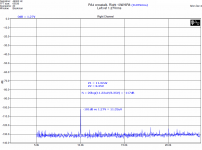
Channel separation was measured with same link cables that are used to connect amp to preamp. Instead of preamp, there was a signal generator. The conditions were absolutely same as if you drive amp fro preamp. Cables, shields, 'loops'. No difference. Generator ground connected to PE. So all possible sources of errors are same as when amp is connected to preamp. Power amplifier has channel separation better than the preamp, so the preamp could not have been used in the test.
Channel separation was measured with same link cables that are used to connect amp to preamp. Instead of preamp, there was a signal generator. The conditions were absolutely same as if you drive amp fro preamp. Cables, shields, 'loops'. No difference. Generator ground connected to PE. So all possible sources of errors are same as when amp is connected to preamp. Power amplifier has channel separation better than the preamp, so the preamp could not have been used in the test.
Last edited:
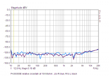
We have often different opinions with PMA, but regarding amp grounding and true dual mono topology advantages, I must support him..In picture is crosstalk measurement ,quite different amp, but with the same dual mono topology and grounding concept. Measured at the same power, 10W /8ohm, crosstalk relative to this level.
Attachments
It is not an empty debate.I am not interested in empty debates. I have results and that's enough for me. You will doubt anything and to me such discussions are a loss of time. Show your results, your measurements and THEN tell me I am wrong. You are a pure theoretician concentrated on limited sort of problems and you never show any results. Debate for debate with no results shown is nothing to me.
You have stated that you connect to ground at one point only, yet your amplifier does so at two.
You have stated that your amp has specific measured results for a specific test. I have pointed out that your test is inconsistent with actual use by the customer.
I have performed tests, and have provided results for discussions I have supported. Recently I have started placing such graphs of actual data within my gallery, as threads such as this are too long.
Do you really believe it reasonable that I must repeat every single solitary incorrect test you audio guys do in order to discuss your errors? Ed tested incorrectly, and all it took was an explanation as to what was done incorrectly for him to re-do the test and get results which were reasonable.
You may claim the debate is empty, but it obviously is not. You simply do not wish to discuss errors in your methodology or understanding.
As to me being a pure theoretician. What a load of garbage, and you know it. I design, build, and test hardware for machines ranging in size from a meter or so out to 27 kilometers, on every continent save 1. One customer did indeed launch a superconducting magnet from Antartica, but there is no installed hardware there I had a hand in.
I am very patiently attempting to teach you what you do not know in order to help you build better product.
If you take away nothing, I do not care.
jn
ps. As to "limited sort of problems", I deal with hundreds of people far smarter than either of us. My job scope exceeds you wildest dreams. (mine too, btw..) I've learned quite a bit over the years, and am trying to spread the wealth. Life will not be long enough I fear.
Last edited:
Nice data.We have often different opinions with PMA, but regarding amp grounding and true dual mono topology advantages, I must support him..In picture is crosstalk measurement ,quite different amp, but with the same dual mono topology and grounding concept. Measured at the same power, 10W /8ohm, crosstalk relative to this level.
Did you drive it with a stereo preamplifier or CD, or did you use only one input as PMA did?
Close the dual IC loop, and run the amp hard into reactive loading. Remember, when you use two IC's, the input signals SHARE the braids. Coaxial cable is NOT shielding when the return current is not equal to and opposite that of the core.
jn
jn, I think what would be helpful for dumb experimentalists like me is some experimental predictions, e.g., "If you take that amp and set it up this way (describe a plausible physical input and output scenario), the errors you've made in grounding will show up at the output as an effect abc."
edit: x-posted where you did the first part of my request
edit: x-posted where you did the first part of my request
Thanks BV, your result is very similar, I think the only difference is measurement sensitivity at lower frequencies. I was doing FFT of the channel under test with FFT referenced to 1.27Vrms (= 0dB), point after point. Then I recalculated the dB result to 8.35Vrms (8.35Vrms/6.8ohm), which was the output of the driven channel.
P.S.: SY, JN, once again, grounding was exactly same as in case of audio chain. No difference. And a preamp inserted between generator and power amp also has not made any difference, if only one channel of preamp was used. It is impossible to use both preamp channels for the reason of crosstalk in the preamp. Preamp has one common PCB for both channels and its channel separation is worse than that of the power amplifier.
P.S.: SY, JN, once again, grounding was exactly same as in case of audio chain. No difference. And a preamp inserted between generator and power amp also has not made any difference, if only one channel of preamp was used. It is impossible to use both preamp channels for the reason of crosstalk in the preamp. Preamp has one common PCB for both channels and its channel separation is worse than that of the power amplifier.
Attachments
Last edited:
Is there any experimental data showing the audible importance of super-low crosstalk, say, better than -50dB?
You already know the answer to that...
My concern is that the arbitrary bench test being used does not simulate actual use. There may be correlation, but they've no idea.
jn
P.S.: SY, JN, once again, grounding was exactly same as in case of audio chain. No difference. And a preamp inserted between generator and power amp also has not made any difference, if only one channel of preamp was used. It is impossible to use both preamp channels for the reason of crosstalk in the preamp. Preamp has one common PCB for both channels and its channel separation is worse than that of the power amplifier.
Well, we are getting there slowly, but at least it is in the right direction.
I had the same problem with Whitlock years ago. For all his testing of inputs, he neglected to consider the outputs of the previous equipment. Finally, in his 2012 presentation, he at least mentioned outputs. Didn't design a test, but at least mentioned it. My testing diagram (of actual hardware btw), is included within my gallery.
Now, think about what is going on in your preamp. There are two parts to crosstalk there.
1. Crosstalk as a consequence of the circuitry within the preamp driving independent and isolated loads.
2.Crosstalk as a consequence of the shields splitting the return path of the signals from the preamp. This crosstalk doesn't exist until the AMPLIFIER completes the ground loop of the IC's. THIS is what I have been speaking about all along.
You need to understand the distinction between the two, and do what you can under the hood of the amplifier to limit it's contribution.
jn
ps. BTW, many of the diagrams from my gallery are from 2004 and 2005. You are being exposed to stuff I posted on the web 8 and 9 years ago. I've been doing this very specific stuff for over a decade now.
Last edited:
Pavel be assured that I don’t find your response as harsh. It’s all technical, not personal. And I respect your work and your contribution here.
This is what I want to convey too. ‘Current flow seeks path of least Impedance - not just Resistance’
Furthermore, the impedance of this loop will vary with frequency.
George
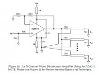
Quoted liberally in the AD8010 datasheet. This different take on bypassing was the result of 2 weeks of board building and experimentation. The diff-gain diff-phase performance for a little 8-legs into 18.75 Ohms was remarkable and at 4.43MHz was demonstrably limited by circulating supply current issues.
EDIT - C1 and C2 are composite caps detailed in the text as well as the vendor on the ferrite beads.
EDIT2 - jn this was 1998
"sigh" the artist might have missed a couple of ground staring issues.Attachments
Last edited:
- Status
- Not open for further replies.
- Home
- Member Areas
- The Lounge
- John Curl's Blowtorch preamplifier part II