Nature of the beast..JN, you are quite curious")
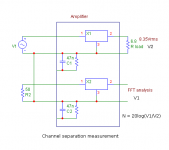
The prototype measured has only unbalanced inputs. It was measured the same way as when it is used for playback, pls see attached image. Regarding internal wiring - that's something I do not want to speak about in detail.
I understand a desire to not discuss details here.
I note several things you may wish to know, but only if you too are curious.
pm me if you wish.
jn
One small notice - If there is a direct connection with chassis, it may be done only at the body of the input connector (speaking about power amplifier).
Which input? You have two, on opposite sides of the chassis.
The line cord safety bond, which input would that be at?
jn
John,
One thing I don't understand in your JC1 design shown above is this:
You have extremely now noise Jfets as i/p devices but these are cascoded with regular mosfets (irf610 & 9610). I would have though have these regular mosfets in the i/p circuit would spoil the low noise performance of the input stage.
Or did I miss something ?
mike
I cant understand why anyone wants to connect casework connected ( for safety reasons ) to mains / line ground - which would very often be horribly polluted - to a connector carrying an incredibly delicate audio signal - would seem so much more logical to keep them separated.
It is extremely logical to keep them separate.I cant understand why anyone wants to connect casework connected ( for safety reasons ) to mains / line ground - which would very often be horribly polluted - to a connector carrying an incredibly delicate audio signal - would seem so much more logical to keep them separated.
On this side of the pond, the National Electric Code requires we bond all metals which may become energized to the safety ground. The NEC does not care about our audio.
So we are forced to work around that. Sometimes we do well, sometimes we do not.
jn
Some of you might ask: Why a 'B' rating, why not an 'A' rating?
Price point, image. It's a fashion industry, with a healthy overlay of make-believe. There's good engineering out there, with things like performance targets and expected use setting the path, but that has little to nothing to do with the dictates of a fashion magazine.
Which input? You have two, on opposite sides of the chassis.
The line cord safety bond, which input would that be at?
jn
I have already shown the circuit, several posts before.
'Opposite sides' - you are referring to a final product with balanced inputs. In case of balanced inputs everything is easy - XLR body is on the chassis and pin 1 should be there as well.
The measurement I have shown was done on the prototype, which has SE inputs only. They are connected through RC to the chassis. R is only to discharge C, so it has high value. Chassis is connected to PE. There is no direct connection of analog grounds to the chassis and there is no LF groundloop. There is no chance to get crosstalk, so the channel separation is as high as it is.
In case you argue that analog ground should be connected directly to chassis, I say not necessarily - there are many laboratory power supplies in metal case that is connected to PE, but all DC outputs are floating.
SY, you know nothing about the audio business. I deeply resent your input on what you are not qualified to have such strong opinions on.
I'll just stare at the ground and drool.
I wonder if you could do a clever mix of "grounded" & "double insulated" to satisfy all safety codes - I have seen consumer DVD players with metal cases and 2 way line cords so there does seem to be some flexibility in this regard.
Of course you can, even the power amplifier can be designed in class II. It is a question of power transformers and internal wiring - double insulation.
I would not care about this. There is another issue, in case you want to be strictly on safe side. These big power amplifiers create AC voltage higher than the 'safe voltage' at their output terminals. We can often see non-insulated binding posts on speakers .....
, this is probaly considered fine I have already shown the circuit, several posts before.
'Opposite sides' - you are referring to a final product with balanced inputs. In case of balanced inputs everything is easy - XLR body is on the chassis and pin 1 should be there as well.
The measurement I have shown was done on the prototype, which has SE inputs only. They are connected through RC to the chassis. R is only to discharge C, so it has high value. Chassis is connected to PE. There is no direct connection of analog grounds to the chassis and there is no LF groundloop. There is no chance to get crosstalk, so the channel separation is as high as it is.
In case you argue that analog ground should be connected directly to chassis, I say not necessarily - there are many laboratory power supplies in metal case that is connected to PE, but all DC outputs are floating.
I was referring to the overall chassis, you provided a picture of the whole thing.
It has the inputs far apart from each other on opposite sides of the back panel, and the outputs directly below the inputs.
You mentioned connecting the input ground to chassis, so I asked which one, or both?
Double insulated is a different animal. That requires far more expertise to get it right.
jn
There is another issue, in case you want to be strictly on safe side. These big power amplifiers create AC voltage higher than the 'safe voltage' at their output terminals. We can often see non-insulated binding posts on speakers .....
Actually, I consider it Darwinism.
jn
You have extremely now noise Jfets as i/p devices but these are cascoded with regular mosfets (irf610 & 9610). I would have though have these regular mosfets in the i/p circuit would spoil the low noise performance of the input stage.
Or did I miss something ?
mike
No noise is added this way. Another thing is important - values of input resistors in the input dividers (sometimes too high, I prefer lower values) and operating current of input JFETs. I am running input JFETs at 8mA and resistors are optimized according to JFETs used. Again, nothing for mass production.
Last edited:
I was referring to the overall chassis, you provided a picture of the whole thing.
It has the inputs far apart from each other on opposite sides of the back panel, and the outputs directly below the inputs.
You mentioned connecting the input ground to chassis, so I asked which one, or both?
Double insulated is a different animal. That requires far more expertise to get it right.
jn
Once again, the photo provided is the final product (with balanced inputs), but today I have measured a prototype that has SE inputs (I have no final product available). These SE inputs have bodies tight to chassis through C//R. The final version has balanced input with XLR's (both) directly on chassis.
Attachments
Last edited:
I cant understand why anyone wants to connect casework connected ( for safety reasons ) to mains / line ground - which would very often be horribly polluted - to a connector carrying an incredibly delicate audio signal - would seem so much more logical to keep them separated.
Mike, if you get rid of galvanic coupling, you have to deal with the capacitive and inductive coupling.
IMO, in the phrase: “a common polluted point of reference for all the circuits in the chain”, the emphasis should be placed at the ‘common’ rather than at the ‘polluted’.
If all the connections to this common point were of very low impedance (thus this point was a true reference common point), pollution there would have no operational consequence.
George
- Status
- Not open for further replies.
- Home
- Member Areas
- The Lounge
- John Curl's Blowtorch preamplifier part II