There are commercial amplifiers that behave very badly when loaded with capacitive speakers (electrostats) or another non-resistive load. Some compromised designs expect they will see resistor 4 or 8 ohm at its terminals. One of the reasons why purely resistive test load does not reveal much. It also splits theoretical designers who play with sims only from real word designers and experimenters. I also agree that a large output coil is bad thing and that it reflects incompetent designer.
There are commercial amplifiers that behave very badly when loaded with capacitive speakers (electrostats) or another non-resistive load.
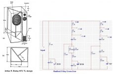
A British “another non-resistive load” example
George
Attachments
about 5uF.
We need very stable amplifiers for this speaker. High feedback factor is a bad thing here.
Above 1KHz the impedance looks a lot like the equivalent circuit shown below.
The interesting question is: Why is that inductance there? It's not because Peter Walker couldn't design a decent transformer. It's there to give a much-needed boost at the top end of the frequency response to compensate for the falling response of the ESL panel itself. The third pic below shows the response of this (admittedly oversimplified) circuit.
Now what's the effect of putting 10uH in series whith that? It gives a fairly broad lift to the treble response - roughly 1dB between 10KHz and 14KHz.
Not at all. It illustrates John's point about output coils perfectly, IMHO.
The Quad electrostatic speaker is but one example. There are much bigger electrostatic speakers that my amps have to drive.
Also, the NEED for such a large output inductor shows a lack of design stability, that should have been fixed in the circuitry.
Agree , cant forget many years ago seeing McIntosh SS Amps letting the smoke out when playing a pr of KLH electrostats and not only on capacitive loads , seen quite a few run for cover even on purely resistive loads ....

Agree , cant forget many years ago seeing McIntosh SS Amps letting the smoke out when playing a pr of KLH electrostats and not only on capacitive loads , seen quite a few run for cover even on purely resistive loads ....
One would think the designers would know their audience better. I think that Cherry 15W amp from 1978 scaled to 100W might have some smoke problems. Those closed-loop output stages with gain remind me of Tigersaurus.
Last edited:
One would think the designers would know their audience better. I think that Cherry 15W amp from 1978 scaled to 100W might have some smoke problems. Those closed-loop output stages with gain remind me of Tigersaurus.
Yah, they do. Tigersaurus had the foldback as well.
jn
Some manual, eh?
They are just so crazy with accuracy. I've the first edition from '88, I'm gonna peruse this one.
Thanks,
Jn
I am very conscious of o/p chokes emitting & picking up EMFs so I went over to toroidals a few months ago. Even so, I like to give the chokes room to work in.
Not sure why air cored chokes have about 10% lower values at 100khz compared with 10khz. 100khz is my top limit.
I normally measure at 10khz
Not sure why air cored chokes have about 10% lower values at 100khz compared with 10khz. 100khz is my top limit.
I normally measure at 10khz
Last edited:
Several things conspire to do this.I am very conscious of o/p chokes emitting & picking EMFs so I went over to toroidals a few months ago. Even so, I like to give the chokes room to work in.
Not sure why air cored chokes have about 10% lower values at 100khz compared with 10khz. 100khz is my top limit.
I normally measure at 10khz
1. Proximity effect within the conductors cause the current within the wires to move to one side. This raises the series resistance because less of the copper is involved in current transport. It also changes the geometry of the coil, reducing the effective size of the coil.
2. External conductive surfaces will create eddy currents as a reaction to time varying magnetic flux trying to go through..lenz effect. As it restricts the volume of space the flux can occupy, it reduces the inductance.
3. If your meter can't handle the Rs rise, it will report incorrect inductance. When I frequency sweep inductance measurements, I look for too high a rise in resistance, as that tells me I'm leaving the accuracy zone of the meter.
I had some roughly 2 uH coils I scanned both on and off a two layer pcb groundplane board to show all this, I thought it was within this thread, but am not sure. I'll try to find it and post it later.
jn

View attachment 389427
No value given for the coil.
Anybody care to sim and graph this with typical L values ?.
Dan.
Very similar network on the old Hafler 220. Any comments on circuits that drive 5uF without any coil, pros/cons? The op-amps with "all cap" drive often compromise other things.
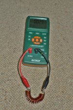
I'd get the leads closer together, close that loop.There are a few things about my LCR meter that are a bit weird:
DCR = 0.03
1 khz Ls 1.2uH, Rs 0.005
10khz Ls 1.24uH Rs 0.009
100khz Ls 1.157uH Rs 0.029
Seems to more confused at 1khz & 10khz
Are the clips copper or steel?
jn
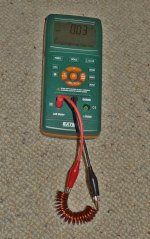
Bit Different but same anomalies.
1khz Ls 1.2uH Rs 0.006 ohms
10khz Ls 1.16uH Rs 0.009 ohms
100khz Ls 1.067uH Rs 0.029 ohms
DCR = 0.03
Oh, I just realized you are questioning the DCR...
You can't worry about the difference between R at freq and dc too much, as the meter will have less accuracy of R while in the L testing mode.
I didn't even think twice about the numbers, to be honest.
What happens if you short the inductor leads using a copper wire in that exact setup? That is meant to measure the test lead inductance.
jn
- Status
- Not open for further replies.
- Home
- Member Areas
- The Lounge
- John Curl's Blowtorch preamplifier part II