I put in my 100 uH standard and it reads 100.03 so I am comfortable with the readings.
ED, please read carefully jneutron's posts you can easily fool the meter and fool yourself. A reference coil has no confounders, negligible series R and parallel C.
I put in my 100 uH standard and it reads 100.03 so I am comfortable with the readings.
Most of these instruments are accurate with low loss reactances like a reference coil or cap. When measuring a reactance in series or parallel with a resistance that is a lot larger than the reactance the accuracy goes down a lot. I had a few of those old bridges but they were a real pain to use and the ESI Videobridge I use now is smart enough to keep me out of trouble. I think both JN and I were really confused by the display on that old Digibridge. We both see mH and you say uH. Enough of an issue to keep me away from one. Something new would be nice but nothing I can get that is an improvement inside my $300 budget for new toys.
Think about what you measured. You are speaking about how the inductance goes as the square of the turns, yet you saw almost no change between lots of turns and none. That in itself destroy's your assertions. It should have raised alarm bells in your head.I put in my 100 uH standard and it reads 100.03 so I am comfortable with the readings.
Then think about the absolute level of inductance. A twisted pair with low voltage insulation will have an effective dielectric coefficient of about 3 to 4. The manu states 55 pf per foot for the cable, which translates into about 50 nH per foot inductance. Yet your meter was showing 7 mH, as opposed to the actual level of 2 to 3 uH. Another point which should be raising alarms.
As I've said, inductance measurements in this range are not easy. Many do not understand the issues and complexities involved. It is not a case of connecting and reading the results in this domain.
Go back and read my earlier posts..inductance meters are really dumb...all they do is push a voltage, and read the resultant current. Then, they attribute the in phase current to resistance, and the 90 degree out current to reactance. It doesn't understand capacitance when in inductance mode.
This is weird, half my post went away. The editor was going funny at the time, who knows..
jn
Last edited:
That is why I explained to Ed the difference between the series and parallel model. He should be using Ls/Rs.Most of these instruments are accurate with low loss reactances like a reference coil or cap. When measuring a reactance in series or parallel with a resistance that is a lot larger than the reactance the accuracy goes down a lot.
And he should be running a frequency scan to verify that the instrument is behaving properly at the range and frequency of interest.
It is important to determine the expected range of the measurement first. When readings are three orders of magnitude off, it doesn't pay to use them to support any arguments. First find out why the reading are so far off.
jn
Something new would be nice but nothing I can get that is an improvement inside my $300 budget for new toys.
This is praised as good. If anyone here has used it, I would like to read some comments
Handheld LCR Meter- DE-5000 Handheld LCR Meter
George
>Edit: Demian, John, when one has to use the Ls/Rs with cables and when the Lp/Rp ?
Last edited:
It won't really replace the ESI Videobridge but would any of the older GR Digibridges. IET has a very good reputation and it is fully specified so its not a hobbyist level product. I would get it if I didn't have the one I have.
I'll let John answer the LS/LP question. I'm interested as well.
I'll let John answer the LS/LP question. I'm interested as well.
>Edit: Demian, John, when one has to use the Ls/Rs with cables and when the Lp/Rp ?
I've always used Ls/Rs for cables, and it has always provided accuracy, repeatability, and consistency with published data from companies like belden, times microwave, etc.
The HP meter I use has a huge manual, it describes when to make the choice. It depends on the relationship between the reactance and the resistance. Too little reactance, and the resistance will swamp the accuracy. Same the other way.
jn
Ref. the above question:
1.Twisted pair
2. Parallel wires
3. Coaxial
George
For me, all use the series model. As you could see, my 150 ohm spaced wire set started to go astray in the 200 KHz range, and if I needed hard data up there for that cable, I would revisit the model. Since it was for a speaker run, I went up to 200khz to assure myself that the meter was reading accurately in the audio band.
For twisted and parallel, it was easy enough to get to within 4% of the terman equation for 6 foot lengths. But it did require re-zeroing a lot to eliminate the test leads to the cable. Ed's setup should have also been re-zeroed after repositioning the cable on and off the spool, as the wires form an open loop at the test instrument (visible in the pictures), and that loop geometry and lay will impact the test accuracy at the 2 to 3 uH level as well.
As I've said, measuring inductance at these levels is not easy, there are so many things that impact the accuracy. Trying to test an 8 ohm cable as I did requires accuracy of readings of 8 to 10 nH per foot, so requires repeatablility at the single digit nanohenry level.
The best I was able to obtain was repeatability at the 250 picohenry level, and trust me, that ain't easy. Unfortunately, I was trying to measure a 60 picohenry current viewing resistor at the time...clearly no joy.
jn
Think about what you measured. You are speaking about how the inductance goes as the square of the turns, yet you saw almost no change between lots of turns and none. That in itself destroy's your assertions. It should have raised alarm bells in your head.
Then think about the absolute level of inductance. A twisted pair with low voltage insulation will have an effective dielectric coefficient of about 3 to 4. The manu states 55 pf per foot for the cable, which translates into about 50 nH per foot inductance. Yet your meter was showing 7 mH, as opposed to the actual level of 2 to 3 uH. Another point which should be raising alarms.
As I've said, inductance measurements in this range are not easy. Many do not understand the issues and complexities involved. It is not a case of connecting and reading the results in this domain.
Go back and read my earlier posts..inductance meters are really dumb...all they do is push a voltage, and read the resultant current. Then, they attribute the in phase current to resistance, and the 90 degree out current to reactance. It doesn't understand capacitance when in inductance mode.
This is weird, half my post went away. The editor was going funny at the time, who knows..
jn
The issue is does coiling a microphone cable have an effect.
You apply circuit theory for R, L, & C. Now as the cable is shielded with a foil shield and is 45' of 22 gauge wire, and I get repeatable changes from coiled vs uncoiled, what parameter do you think is changing?
Even if we measured fuzzywumples and that showed repeatable changes, does that not indicate that there is a difference?
Now as the cable is shielded with a foil shield and is 45' of 22 gauge wire, and I get repeatable changes from coiled vs uncoiled, what parameter do you think is changing?
Voltage induced through magnetic coupling
")
The issue is does coiling a microphone cable have an effect.
You apply circuit theory for R, L, & C. Now as the cable is shielded with a foil shield and is 45' of 22 gauge wire, and I get repeatable changes from coiled vs uncoiled, what parameter do you think is changing?
Even if we measured fuzzywumples and that showed repeatable changes, does that not indicate that there is a difference?
As I continue to repeat to you, it is very important to understand what you are actually measuring. You do not know what your readings mean, as you've no understanding of how the meter arrives at the number it displays.
Do you think the foil shield is doing anything to a magnetic field at 1Khz? Do you believe it is a 100% shield for capacitance?
Do you believe Lp/Rp is the most accurate way to measure that cable?
Did you zero out the loop at the test terminals as well as the open independent wires where you've splayed them out of the twist?
You mis-applied the turns vs inductance relationship to the problem at hand, because that equation only applies to current flowing only one direction in the cable. Since you are pushing current in both directions, there is no net solenoid, so that equational relationship does not hold.
You're measuring two co-mingled solenoids here, and they are magnetically opposed.
Your test measurement error bands swamp out what you are trying to measure. Your data cannot be trusted, no matter how many times you repeat it.
I point out all of your measurement errors, they are over 4 orders of magnitude larger than what I've consistently done. Why do you still insist that what you are measuring is real?
jn
I have a pretty good idea of what I am measuring and have shown a simple demonstration of a repeatable difference. I did not and do not claim to be measuring inductance by itself.
The reason why I mentioned the foil shield is that although a common technique it has well know issues. It does come into play on capacitance measurements.
Parallel mode was the best way to show the delta in readings.
I thought I mentioned the test equipment is operating correctly.
The actual major issue is that of "co-mingled" solenoids. I suspect that there is an unbalance in the co-mingling due to the actual cable construction which is why coiling the cable induces changes. If there is such a tilt the that tilt would follow turns squared. As far as I can tell that is the actual issue at hand.
Now in a portable microphone cable the shield is woven and although thicker has less coverage. If I get the chance I will run frequency response curves on such cables; straight, coiled and on a metal spool. Using a 150 ohm source resistance and 1,000 ohms or higher load would be typical of a microphone in use. Phase shift of 5 degrees at 20,000 hertz is considered the hearing limit by both Schroeder and Neve, so there is a clear target.
BTY before eBay and being able to afford test equipment I built my own. An impedance bridge was one of them. The fanciest piece of gear I built was an audio band Fourier transform system. I still have my .05% resistors and other standards I used to calibrate thingys.
Last edited:
The issue is does coiling a microphone cable have an effect.
You apply circuit theory for R, L, & C. Now as the cable is shielded with a foil shield and is 45' of 22 gauge wire, and I get repeatable changes from coiled vs uncoiled, what parameter do you think is changing?
Even if we measured fuzzywumples and that showed repeatable changes, does that not indicate that there is a difference?
I would guess inductance , but this is freq dependent , would this show on a simple meter ..? You would have to measure thru the audio band ..
If there is such a tilt the that tilt would follow turns squared. As far as I can tell that is the actual issue at hand.
I think what jn is saying is that there is not yet justification for using the solenoid equation. You and Demian are still 1000x apart. 6mH and 2k would certainly be some phase at 20k
I think what jn is saying is that there is not yet justification for using the solenoid equation. You and Demian are still 1000x apart. 6mH and 2k would certainly be some phase at 20k
Please sit down... I will agree with you on that!
I was just showing there is a difference between coiled and uncoiled. Now a valid question is there enough difference on 250' of microphone cable to actually be heard. So since I have all the gear I'll run a frequency phase plot set.
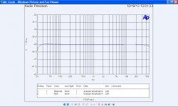
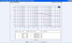
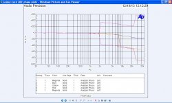
Here are the results of 200' of portable mic cable. I ran the F plots at 10mV but stepped the phase up to 10 volts as the AP seemed to lose it's grip on reality.
The most important band is around 5,000 hertz and the coiling seems to reduce the phase shift there.
The most important band is around 5,000 hertz and the coiling seems to reduce the phase shift there.
Attachments
Last edited:
Jneutron
Thank you for answering.
Although this discussion doesn’t fit my size, I was involved, because I have experienced myself the issue of silly cable readings with one of my LC cheap digital meters
I had to go to some equations (here is the online version Clemson Vehicular Electronics Laboratory: Transmission Line Impedance Calculator) to see what the “expected” measurement should be.
I understand that the issue of a meaningful L/C reading is equally difficult with advanced LCR measuring instruments.
See below (page 42-47, 52-58, 84, 99-115) for some very useful data and info that have to be considered when measuring L/C
http://cp.literature.agilent.com/litweb/pdf/04275-90001.pdf
George
It doesn't matter how many times you repeat a flawed test.I have a pretty good idea of what I am measuring and have shown a simple demonstration of a repeatable difference.
You are using the metric "inductance" as viewed on a meter, to confirm your assertion of a "change". You explained it via the solenoidal inductance equation, which was a misapplication.I did not and do not claim to be measuring inductance by itself.
You have no control over the measurement, you've no idea what the meter is reporting to you. The meter light in the pictures indicates it is in the mH range, and it is reading 6.9xx, you said earlier microhenry, but the meter display says mH. What is it?
The reason why I mentioned the foil shield is that although a common technique it has well know issues. It does come into play on capacitance measurements.
Ed...it comes into play on inductance measurements.
So you chose an incorrect mode because it agreed with your preconcieved notions??? That's not how it works..Parallel mode was the best way to show the delta in readings.
The equipment is doing what it is designed to do. If you selected a measurement model which is inconsistent with proper and valid measurement practice just because you didn't like the results, then you are guilty of compromising the intellectual validity of the test.I thought I mentioned the test equipment is operating correctly.
The net solenoidal current is zero. The two solenoids are extremely well coupled by the nature of the twisted pair of the conductors. You continue to neglect the confounders I and others have told you about.The actual major issue is that of "co-mingled" solenoids. I suspect that there is an unbalance in the co-mingling due to the actual cable construction which is why coiling the cable induces changes.
If there is such a tilt the that tilt would follow turns squared. As far as I can tell that is the actual issue at hand.
No, it will NOT. What part of no do you not understand. The solenoidal equation comes into play when the cable has a net non zero sectional current. It never does in your setup.
jn
Ed. The most important thing for you to understand with your plots is this: Your plot goes from darn near zero degrees to 800 degrees between data points? And that doesn't raise alarm bells in your head??? And yet the FR plot is darn near flat through the entire range?Here are the results of 200' of portable mic cable. I ran the F plots at 10mV but stepped the phase up to 10 volts as the AP seemed to lose it's grip on reality.
The most important band is around 5,000 hertz and the coiling seems to reduce the phase shift there.
That in itself should tell you that you have a test setup problem. You are not measuring what you think you are.
I most certainly have a problem with how you present data as well. You have 5 lines on a plot, with absolutely no textual information as to what it is..
Also, how are you controlling shield currents? What is your test schematic, did you terminate both ends of the cable at the same piece of equipment?
jn
Last edited:
- Status
- Not open for further replies.
- Home
- Member Areas
- The Lounge
- John Curl's Blowtorch preamplifier part II