davym,
Or anyone else could you explain to me how an optical link can remove the ground plane induced noises or any other noises that I would assume are superimpose over the original signal earlier in the chain? It would almost seem like a Bybee device type of situation where the question is how does the optical link distinguish what to reproduce and what to remove? Is this just a bandwidth limiting situation removing any extraneous noise outside the chosen bandwidth?
An optical link breaks the ground loop that can be formed by the wires, and the fiber is impervious to magnetic fields. But you are correct, once in, it's in.
Ground loop mitigation is in three basic parts.
Stop the source of the ground loop current.
Stop the coupling of the current.
Stop the sensitivity to it.
Do all three where possible. Even if only one part is done well, the issue is gone.
jn
I was going to say it breaks the ground loop but clearly it is best to stop it at source. It's a trade off having to use the extra circuitry involved in the optical link, I would have preferred not to but it's not an ideal world sadly. A better way is to not use SMPS at all IMO.
1. … While I've posted on at least 3 sites a complete descriptor with diagram of the setup, I've seen nobody take it up.
You see nobody because we amateurs are working in our caves

3. Everybody assumes the output section of a source component is impervious to ground loop currents, which is incorrect. While it may not amplify the coupled signals, it will still present it to the input of the next piece of equipment.
Not everybody. (Richard has posted some scanned relevant diagrams)
4. The distinction between bench testing of an amplifier using well isolated test gear, and that of amplifier operation in situ using equipment which is not well isolated is lost to most. I've provided test diagrams of that as well over the years.
True (painfully true). I do thank You and AndrewT for pushing this red button repeatedly over the years.
5. …To produce any semblance of soundstage, ITD and system generated ITD errors must be considered.
IMO, such time differences btn channels can only occur in the acoustic domain (performers/microphones/venue, speaker/room/listener) and in some cases at the tip of a turntable cartridge.
George
I am in the next cave over.You see nobody because we amateurs are working in our caves
Any chance of pointing where? IIRC, he also did some stripline supply stuff decades ago that I was unaware of.Not everybody. (Richard has posted some scanned relevant diagrams)
IMO, such time differences btn channels can only occur in the acoustic domain (performers/microphones/venue, speaker/room/listener) and in some cases at the tip of a turntable cartridge.
George
You would be surprised. First, if a power amp creates ground loop currents due to supply rail currents, and that current finds it's way into the signal chain upstream, there can be significant loss of phase margin (been there, done that...boom went the tweeter caps), or simply timing changes to some aspects of the audio. If the rail currents couple through the supply bridge, then you end up gating the currents through the diode conduction ontime.
Remember though, it's not a whole channel delay to worry about, but rather, if some frequency components are delayed where others aren't as much, that plays with the imaging.
Best bet is to attack all three aspects, then be done wit it..that way, you don't have to worry about all the different modulation types and coupling paths. That stuff's just a bunch of hooeeey anyway..I myself have better things to worry about.
Like where to get blue cheese stuffed olives for my martini..
jn
Tom van Doren's presentation is really good and I think accessible. I have a demo board for a DAC on my bench and have tried it with both linear and switching supplies. Until I got the ground currents managed such that they did not share the audio ground there were big differences between the different supplies (at the -110 dB level). Once the grounding of the supplies and the DAC were sorted the differences vanished as they should in this case. Implementing in a system would be more difficult. The switching supply is a Cosel module that seems pretty good to start with.
He gave a two day seminar on EMC here a few years ago to about 150 engineers and physicists. While what he teaches is logical and understandable, most of the guys had no clue as to EMC issues and practices, so they really learned a lot.Tom van Doren's presentation is really good and I think accessible.
Me, I learned nothing new.
Course, that's because I'm brain dead. Drowned too many olives.
jn
While I seriously doubt that anything on this planet can be called off topic within this thread, I wanted to post a tidbit regarding this statement.IMO, such time differences btn channels can only occur in the acoustic domain (performers/microphones/venue, speaker/room/listener) and in some cases at the tip of a turntable cartridge.
George
Here is the t-line analysis of a 100 ohm line fed by a low impedance source into various load impedances.
Note that despite the fact that it is only 20 feet long therefore incredibly short with respect to audio wavelengths, the settling delays reach quite far into the human ITD thresholds. And that is neglecting the rise in impedance typical for cables in the audio range, as real t-line impedances are factors of 3 to 4 higher there, which scales the delays proportionally so.
Delaying a specific band of frequencies of an image on both channels where the panning IID has placed the image significantly off axis results in a placement shift of those frequencies with respect to the primary image component.
Too many believe that the propagation speed of a cable defines how fast all signals will flow through it. That is only correct when the signal has the voltage and current relationship consistent with the cable's impedance. Speaker loads and zip cord type wire do NOT propagate the total energy to the speaker at the line's propagation speed. It settles based on the line to load/source ratios. Cyril Bateman actually displayed this via a modified RF bridge.
jn
Attachments

Last edited:
Now you can understand how difficult it is for me to learn new things about audio design from inputs here, or in 'Linear Audio'. '-)
Oh, then just disregard that stuff on resistor selection in Linear Audio Vol. 1.
Oh, then just disregard that stuff on resistor selection in Linear Audio Vol. 1.
um, simon..I think he was joking. Referring to the drowning of olives (or onions) I believe.
jn
Now you can understand how difficult it is for me to learn new things about audio design from inputs here, or in 'Linear Audio'. '-)
Some here have confidence that you can learn new things.
Now you mention it, I do have a spare tone arm which I could conceivable find a way to mount well enough for this sort of experiment. I have a couple of old cartridges too.spend a day to build a simple/cheap/good second arm which can even be mounted without any modifications, outside of your TT plinth
I was thinking of wow & flutter, particularly the latter, which are present in all turntables to some degree, and are often audible. I suspect that W&F are greater than speed variations that result from variations in drag from the stylus, but then I haven't done the experiments. Maybe others have, but I've never seen results.Nominal rotational velocity offset and long term rotational instability... is not easily acoustically detected or annoying.
It truly is amazing that the darn things work at all!With TTs, there is a bunch of mechanical elements –masses/springs/compliances, distributed within the materials or discrete at the interfaces-that have to be functionally balanced in amplitude, frequency, phase.
All true, but I would also suggest that the basic performance parameters, like rumble, wow, and flutter, generally fit into a pretty narrow envelope for a very large number of turntables in a broad price classification. While, as you say, there are a number of things that affect the audibility of these parameters, and ways to mitigate some of them, I find it interesting that those who most insist on the importance of things like "needle drag" usually prefix "micro-" to the effect ("micro-speed variations caused by micro-changes in drag with varying groove modulation"), while the speed variations that are always present are more "macro" than "micro" (somewhere in the range of 0.1% ?).As soon as you start digging, you will realise there is no such a thing as a “typical TT”
Of course, I enjoy playing records on my turntables too, or I guess I wouldn't spend so much time messing around with them. It's great fun trying new things, tuning, building, changing. George, I really admire you willingness to measure and back up what you do with real data, as opposed to "that sounds a little better to me". What is that wonderful Dutch phrase? "Meten is weten als je weet wat je meet", or something like that.
jn, thanks for putting up that material. I've gone nuts at various times over the years trying to get a handle on these sorts of influences, and resolving issues is still very much a black art, when you're dealing with the finished components, that happen to be part of a working system. Pretty crazy experiments done, with results where one ends up going in complete circles, with no net gain ...
For me:
1. There are no valid repeatable test regimens yet used in industry to determine the full bandwidth ground loop current susceptibility for audio equipment. Whitlock does force pin 1 current, but limits bandwidth and still considers only IR drop, to date never considering the inductive mutual coupling. While I've posted on at least 3 sites a complete descriptor with diagram of the setup, I've seen nobody take it up.
2. There are no valid repeatable test regimens yet for measuring full bandwidth ground loop currents created by audio power equipment.
3. Everybody assumes the output section of a source component is impervious to ground loop currents, which is incorrect. While it may not amplify the coupled signals, it will still present it to the input of the next piece of equipment.
4. The distinction between bench testing of an amplifier using well isolated test gear, and that of amplifier operation in situ using equipment which is not well isolated is lost to most. I've provided test diagrams of that as well over the years.
5. Very few people account for the sensitivity of humans to ITD at the 2 to 5 uSec level, and confuse that entity with an inverted bandwidth of darn near half a Mhz. To produce any semblance of soundstage, ITD and system generated ITD errors must be considered.
Cheers,
jn
I see from your diagrams that one way at least to reduce ground loops is to tie or wind interconnects and mains cables together. That is a hard sell to people who have been told time and again to give plenty of space between the two, and if they do have to cross make sure it is at a 90 degree angle
.Regards,
Rob.
Absolutely. the concept is so counterintuitive that many just ignore it.I see from your diagrams that one way at least to reduce ground loops is to tie or wind interconnects and mains cables together. That is a hard sell to people who have been told time and again to give plenty of space between the two, and if they do have to cross make sure it is at a 90 degree angle
Regards,
Rob.
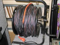
It works extremely well however. I actually made a snake using a 100 foot extension cord, a mic cable, and a single ended line level cable, wrapped the three together and put braid over it. It remove all traces of noise and hum. I knew that concept worked for me previously, it followed theory, but I still marveled when I put it together and the darn thing worked perfectly. My roadies loved it as well...they were 10 and 12 years old at the time.
Here it is. I'll add it to my gallery as well.
And NO comments about the power puff girl wrapping paper!!
jn
ps. Just try not to have the twist pitches of the cords match the twist pitch of the extension cord. That would negate cancellation by common centroids, and even a balanced cable would communicate with the line cord currents.
Attachments
Last edited:
No braid. Just loosely wrapped around each other.JN,
Should we assume that you braided those three cables before you covered them or are they truly running parallel to each other? I'm voting for braiding from some of your past comments on power supply wiring.
Almost parallel.
Don't forget, the line cord has it's twist pitch, the mic cable has another, and the stereo line level cable is the same as the mic cable. The line level cable is actually 125 feet of mic cable, but I run left and right inside the same cable, with a common shield return. Not the best setup for prevention of crosstalk, but the spool wouldn't hold an additional 125 feet of mic cable to make left and right balanced.
The only concern is to make sure the twist pitches between a balanced cable does not conspire with the line cord pitch and magnetically couple. Cat5e cable does that, they have 4 different pitches internally to prevent magnetic coupling inter-pair.
If you run a dingle ended coaxial cable with a line cord which has twist to it, you don't even worry about twist, just put them together. My case was a tad special only because in the mic cable, neither core wire is coaxial to the shield, so there is a very small possibility that they accidentally communicate if pitches are the same.
jn
- Status
- Not open for further replies.
- Home
- Member Areas
- The Lounge
- John Curl's Blowtorch preamplifier part II