The nice thing about this test record is the 300Hz bands at beginning, middle, and end, so that the alignment can be set to try to minimize distortion across the disk, useful for us benighted souls who don't have linear tracking arms.
SY
The same with "HFN Analogue Test LP", 2002 release.
Side Two, 300Hz L+R at +15dB, bands 1, 4, 8.
(0dB should be 5cm/s for lateral modulation but there is no explicit reference of this in this test LP)
Scott…and I have seen no test LP with better than several percent distortion at higher modulations.
See Fig. 5 Good Resolutions - Page 2
But how can you say if this high distortion is on the test record or is due to cartridge reading the track?
George
Last edited:
But how can you say if this high distortion is on the test record or is due to cartridge reading the track?
George
My point, in the LP world you do not have a clean reference to refer to. If even 1% is your baseline how do you compute out the fortuitous additions and subtractions of all the other distortion mechanisms? That is you measure a net 1% where is that from?
No, Scott, you are 'double blind'! I say it is better to 'peek' than to be 'double blind'. '-)
I know the price for not peeking is unbearable.
Well, this is the 40th year since I developed the complementary differential jfet line amps for the Grateful Dead. Yesterday I got a book: 'Grateful dead Gear' 1965-1995 by Blair Jackson, a GD roadie. I knew Jackson when I worked with the GD, and he always treated me OK. Anyway, the complementary differential input stage based line amp was described in this book, along with the rest of the gear for the 'Wall of Sound', originally developed in 1973. I am thinking of showing a few jfet input stage topologies that have been extra successful.
Do you have anything new to show? I have always gone out of my way to recognize your past contributions as I have of those like Bob Pease, but if you really think that no one has contributed anything since beyond wire directionality, cryo-treatment, etc. why not just say it.
Scott, I would appreciate it if you ceased to criticize my inputs. I personally don't care if YOU care about what I have to input, or not.
The truth is: I developed a number of topological solutions in the 1970's that are often 'rediscovered' today. Now, I will show some of these topological solutions for others to learn from.
The truth is: I developed a number of topological solutions in the 1970's that are often 'rediscovered' today. Now, I will show some of these topological solutions for others to learn from.
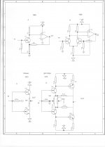
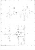
A few examples: (simplified without proper biasing in some cases)
More advanced examples, later.
Your 1972 gain stage will not work properly...
Ok, so a couple of typos got through, we get John's message.Your 1972 gain stage will not work properly...
Dan.
Last edited:
What would the opamps have been back in 1968 assuming they were IC's and that the opamp symbol isn't depicting a discrete or hybrid gain stage ?
Bob Pease was doing them in 1963, and Dick Burwen at least by 1966. Interestingly the little triangle symbol is pretty old in the analog computing world.
Thanks Ray and Max. I did miss the typo.
The triangle symbol is what the computer defines as 'op amp' in the drawing program, but it can represent following gain stages as well.
Before the uA741, and LM301, we also had the uA702 and the uA709, both designed by Bob Widler, first with Fairchild, later with National.
The triangle symbol is what the computer defines as 'op amp' in the drawing program, but it can represent following gain stages as well.
Before the uA741, and LM301, we also had the uA702 and the uA709, both designed by Bob Widler, first with Fairchild, later with National.
OK, a fast critique of the different types of jfet input stages:
A is the traditional approach in the 1960's for audio. It is potentially fairly quiet, but it has no significant power supply rejection, is usually used with single supplies, and is somewhat 'awkward' to bias. Cap coupling is usually mandatory.
B is the easier to build choice, BUT it is usually 3 dB noisier than A. It has the advantage of direct coupling and better power supply rejection.
C is really just a complementary follower, but it is interesting how it is similar to D which came later.
D is where new ground is being made. The self biasing nature of the jfets is used here to make a simple, yet elegant input stage, with balanced drive to the second stage.
It's drawbacks can be difficulty in keeping it temp stable and initial set up. This is still a very high quality input stage, if chosen. The complementary fets are in 'noise parallel' so they potentially REDUCE input noise, contrary to the simple differential pair that INCREASES input noise.
- Status
- Not open for further replies.
- Home
- Member Areas
- The Lounge
- John Curl's Blowtorch preamplifier part II