...
I do like that Al2O3 board, it's a great heat spreader.
jn
Yep, mostly unappreciated until you hand solder on it.
Thanks
-Antonio
differences
You talked of evolution, human hearing capabilities, comparisons btw A and B. Wouldn't be great if someone took an amp with the least amount of distortion and then add a list of distortion could be added to the output signal and then ask people to pick which one the enjoyed? Then the distortion could be given a name and distortion could be categorized by their taste of music. I think you should read a book I just finished. "Black Order" by James Collins. I think you would love it. And while reading it, I thought all the sciences that gave the book meat was all made up--wishful thinking, but it all had a true existence (history given at the end of the book). It talked about quantum theory and how subatomic-particles would change from particle to energy when it sensed it was being observed or under any type of measurement.
I can't remember the name, but the audio tech, Japanese I think, said that it wasn't the device's output that one person desired (doing everything to remove distortion), but the distortion. A Marshall guitar tube amp with a sick tube? Where would Santana be without one? Cool uh?I think that a personal approach to audio design is appropriate at this point.
It is true that double blind tests and some differential tests make sonic quality to appear rather easy, and all that we should care about is our listening rooms, more or less. This is an alternative belief system that has not convinced me to give up serious audio design, but it has deterred others from going forward.
Now why do I hold to my belief that audio differences, small in actual acoustical error, are still audible? Well, it is because of my experience with comparing different audio products.
People think that level matching was 'invented' by double blind testers, BUT we were doing it more than 40 years ago, seriously. This was especially important to me, because MY audio amp lost, in comparison to a triode amp with the same frequency response, distortion with level, distortion order, and damping factor. In fact, we did a differential subtraction of the two amp outputs, to get the levels matched. YET, I preferred the TUBE amp, and not my own! However, I TRUST my ears, and I didn't give up, I just kept looking further.
When ABX testing came out over 30 years ago, I tried it as well, and I could not hear a difference between one of my own designs and a Dyna tube preamp. What happened, was there no difference? NO, because the differences came back, as soon as I removed the ABX equipment. This was as start as to what the problem was, but not the only thing. However, I am not a psychologist and I can't (or won't try) to explain here what I think is the fundamental problem, but I know personally that double blind tests remove (for me) every vestige of subtlety in the sound. To continue to use double blind tests meant that I had to blind myself to hearing differences, differences that others could hear, and not just me. It just wasn't productive to do so. I stand on the evolution of my designs for the past 30 years as proof that I did the right thing.
Now, when it comes to differential subtraction, it sometimes works well, BUT actually, other tests will bring out more difference, why I don't know. The human ear is an incredible mechanism that seems to hear differences that measuring equipment cannot, so long as people are free to listen openly and compare. Even A compared to B is OK, behind a screen, and that should be enough for anybody. It works for me.
You talked of evolution, human hearing capabilities, comparisons btw A and B. Wouldn't be great if someone took an amp with the least amount of distortion and then add a list of distortion could be added to the output signal and then ask people to pick which one the enjoyed? Then the distortion could be given a name and distortion could be categorized by their taste of music. I think you should read a book I just finished. "Black Order" by James Collins. I think you would love it. And while reading it, I thought all the sciences that gave the book meat was all made up--wishful thinking, but it all had a true existence (history given at the end of the book). It talked about quantum theory and how subatomic-particles would change from particle to energy when it sensed it was being observed or under any type of measurement.
No problem.
(i'll get back to you for a rain check, once i've finished harassing another EE
 )
)Wouldn't be great if someone took an amp with the least amount of distortion and then add a list of distortion could be added to the output signal
Already been done a quarter of a century ago.
This reminds me of the tube power vs transistor power controversy, perhaps 45 years ago.
Then, we were told that the first T0-3 complementary output transistors were rated at 150W each. A few years later, the same size package generated 300W max from selected Motorola devices.
Now, how was this power rating determined?
Would you believe with an INFINITE HEATSINK? Or perhaps tested with a 'swimming pool' of Freon surrounding the device?
How big an amplifier do you think that you could normally get from a pair of the initial power transistors with a REAL heatsink? At first maybe 50W, a little later, maybe 150W, with advanced protection circuitry added, that came on fairly regularly with a REAL SPEAKER LOAD, and greatly reduced the subjective power output to less than a 75W tube power amplifier.
What about a tube output stage? Well, a pair of KT-88's could easily do 60W in a cheap and simple circuit, and 75W in a McIntosh power amp. Yet the individual ratings might be 42W each. How can this be?
Can you see that it is the WAY the devices are rated?
The solid state rating is useful, only IF you understand that you well never get there for any length of time, depending on the heatsink used, which could be extensive.
I would compare the 'specs' of surface mount power devices with the same skepticism that might have a useful rating, IF you understand the limitations, but you cannot replace square inches of heat transfer, any more than you cannot reduce cubic inches in an automobile, without serious tradeoffs.
Was the panel fed delta or wye? Excessive neutral pull could cause overvoltages. Given the waveform shown with the dead just in front of zero crossing, I'd first look at the neutral currents.
Reminds me of Zsa Zsa trying to add single digit numbers so she doesn't blow the generator out.
jn
Eva not Zsa.
Wye, but voltage shifts wouldn't affect the switchers other than to increase the current on the ones with low line voltage.
The claim is the breakers "Melted" from the harmonics. How much over current would it take to melt a breaker?
I thought at first they were talking about magnetic breakers where if you had high harmonics the coil could overheat. If there were no thermal element that could be possible. However as the harmonic distortion is 8.6% that drops the issue very close to 0.
Yep, mostly unappreciated until you hand solder on it.
Thanks
-Antonio
Most definitely.
For rework of those puppies when they are soldered down with eutectic tin/lead, I'd preheat the board on a hotplate to about 150 degrees C, then use a pencil iron to heat individual pads.
For eutectic tin/silver, I think it would require about 200 C preheat for any rework.
John
Now, how was this power rating determined?
Would you believe with an INFINITE HEATSINK? Or perhaps tested with a 'swimming pool' of Freon surrounding the device?
How big an amplifier do you think that you could normally get from a pair of the initial power transistors with a REAL heatsink?
Perhaps they assumed that actual engineers can read data sheets and do basic thermal calculations.
likely measured with copper cold plate with cooling water pipes - the specs do say: "25 C case temperature"
and probably elevated to a top line bold/bullet item by some marketing genius
once you realize the test conditions its easy to apply a factor of say 50% for what a farily good convection air cooled heatsink could do with the part
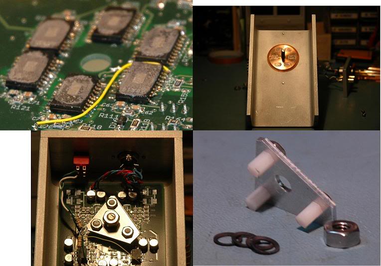
I am sucking > 6W from each TPA6120 op amp by clamping its power pad to a copper slug PC cooler:
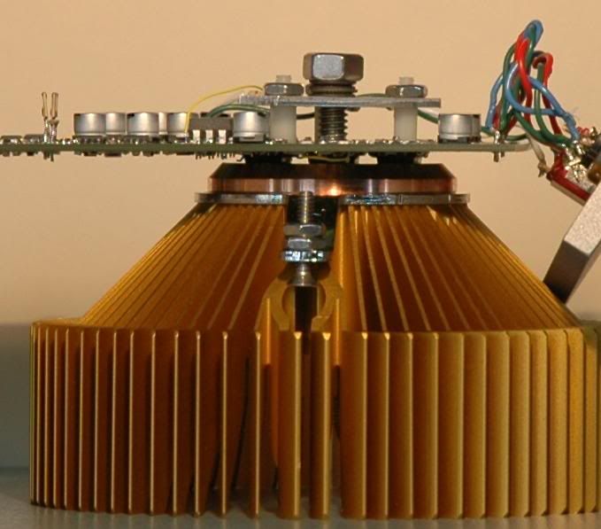
side view of 6x TPA6120 mounted "belly up" to clamp pwr pad to CPU heatsink Cu slug
internals:
and probably elevated to a top line bold/bullet item by some marketing genius
once you realize the test conditions its easy to apply a factor of say 50% for what a farily good convection air cooled heatsink could do with the part
I am sucking > 6W from each TPA6120 op amp by clamping its power pad to a copper slug PC cooler:
side view of 6x TPA6120 mounted "belly up" to clamp pwr pad to CPU heatsink Cu slug
internals:
Last edited:
This reminds me of the tube power vs transistor power controversy, perhaps 45 years ago.
Then, we were told that the first T0-3 complementary output transistors were rated at 150W each. A few years later, the same size package generated 300W max from selected Motorola devices.
Now, how was this power rating determined?
Would you believe with an INFINITE HEATSINK? Or perhaps tested with a 'swimming pool' of Freon surrounding the device?
John, if you have no knowledge on a subject, PLEASE do NOT expound on it. It's foolish looking.
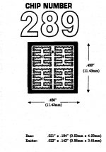
The limit on a transistor dissipation is based on the temperature that occurs on the top of the die. All of the dissipation in a bipolar in the old days was within the top thousandth of an inch of the chip, that is where all the diffusions are. That is where the CB/EB junctions are.
Early limits on die dissipation? How much of the top area was actually dissipating... Emitter finger patterns, aluminum thickness, where the emitter bonding pads were and how many... all change the dissipation distribution. Check out solitron, they have die pics readily available online. I worked with the 4 emitter pad, half inch square chips..I forget if it was the 068 prefix die ...back in '83.
Another heavy limit on dissipation is the attach bond to the chip bottom. In the early days, they'd use a die attach preform (maybe the RS type, or "rapid solidification" where they cool the molten solder on a spinning copper surface to the tune of 10k degrees/sec), I recall Moto had a proprietary 4 component alloy, and I believe they used a nitrogen belt furnace. I don't believe they used a DAP process, but then again, that was a while ago.
How did they determine the limit?? Easy. They measure it.
A circuit which forces dissipation on the transistor, then turns off for 100 microseconds or so...during the short turnoff phase, measure either the EB or CB forward voltage with a 10 or 100 microamp current source.
The time constant from junction to case is well into the 10's to 100's of milliseconds. Settling time to get a temp read is in the 10 uSec range, so they can get a read of the silicon temperature physically within a thousanth of an inch from the top surface.
They make and sell testers like this commercially. Back in 84, I had to build one. Mine was a little different, in that I used the measured temperature to modulate the power dissipation. I could detach the device case from the heatsink during high dissipation, and the circuit would adjust the dissipation to maintain constant die temperature.
They also overcame many early secondary breakdown problems due to hot bonding voids (a void under the transistor die). This is production tested with a high power pulse to determine transient thetaJC ..some will subject the units to BVceo(sus) to cull out secondary breakdown faults as well.
John
ps..device ratings are always junction to case. The manu could of course cheat by putting the case thermocouple directly under the die to give better numbers. But that seldom gets repeat customers.
Attachments
Last edited:
No problem.
(i'll get back to you for a rain check, once i've finished harassing another EE
no problem, i'll save a little angst till later just for you

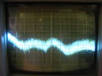
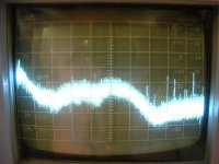
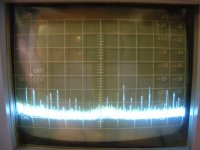
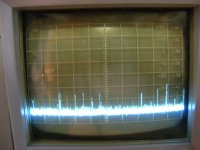
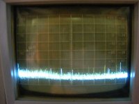
Well let me troll a bit and show the RF noise passing into a power supply.
First is the noise out of a 2 x 12 VRMS 12.5 A Toroid connected to the power line.
Next is with my noise generator turned on.
The third is with a center tapped dual diode rectifier feeding a 4700 uF filter cap.
The fourth is with an added .01 uf ceramic disc capacitor
The last is with a full wave bridge to limit the RF conduction time.
Attachments
any more than you cannot reduce cubic inches in an automobile, without serious tradeoffs.
Chrysler Turbine of the early '60s.
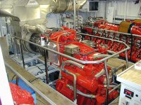
Picture of a yacht engine room.
The silvery thing in left top center weighs 1500lb, does 5600hp.
Each of the diesels on the sides weighs 20.000lb, reaches 2/3d of the little one's power level.
OK, so a MiniMe costs four times the 1 million dollars of the heavyweight, not a serious tradeoff for some.
(bet you a million bucks there will be newlywed gasturbine cars again)
Attachments
Last edited:
Wow discussing old audio power transistors on page 3770!
JN the banner was 150 watts, they had to do AP notes to explain how to derate this. It took a few years for that part to be well known. Tube power ratings were better understood because quite simply they didn't need heatsinks.
I still have some nice extruded TO-5 heatsinks.
If you think the issue is clear even today try getting a guaranteed number for the thermal resistance of a greased mica washer.
SY, If you think thermodynamics are really considered, the use of linear thermal resistor values should make it clear they are not done accurately.
Well let me troll a bit and show the RF noise passing into a power supply.
First is the noise out of a 2 x 12 VRMS 12.5 A Toroid connected to the power line.
Next is with my noise generator turned on.
The third is with a center tapped dual diode rectifier feeding a 4700 uF filter cap.
The fourth is with an added .01 uf ceramic disc capacitor
The last is with a full wave bridge to limit the RF conduction time.
Ed, this way I am tuning my preamps and power amplifiers for minimum HF content at their outputs. Caps from RCA-jack grounds to chassis, types of cables used, grounding schemes, and stuff like this. One can reduce occurrence of HF spikes at more than 20dB. This is, IMO, almost most important for "good sound". Even milled case from a single block of Aluminum may not help, if all other good practices of HF rejection and HF input along cables rejection inside the box are permanently overlooked. One good example of overlooking of HF design principles is at the beginning of part I of this thread, with photo attached.
Um, Ed. You can't get a guaranteed number for that.If you think the issue is clear even today try getting a guaranteed number for the thermal resistance of a greased mica washer.
Remember, it's not the bulk washer thermal resistance which is used, that would be it's conductivity and the total area. The thermal resistance of any washer will be dependent upon the heat spread above it in the package. a case with a bottom thickness of 40 mils will run hotter than a case with bottom thickness of 100 mils.
To get a rough idea of what it will be, you take the die size, add twice the package bottom thickness, then use that area for a thermal resistance calculation.
If the die is .250, like a IR450, a case bottom of .040 give an effective thermal area of .330 by .330.
If the case bottom is 100 mils, the effective area is .450 by .450, an area increase of 85%, and a thermal resistance decrease of 45%.
If you can't tell them what the effective area is to use in the thermal resistance calculation, then you can't expect them to give you a thermal resistance.
jn
Perhaps they assumed that actual engineers can read data sheets and do basic thermal calculations.
Leaves me out. I ain't an actual injuneer..
jn
SY and JN, I don't appreciate being criticized about what I know about semiconductor temp. ratings. In 1969, I built at Ampex Research, a 2000W motor drive amp that used multiple pairs of the 300W devices that I mentioned previously, as well as a full complementary differential input and a balanced balanced bridge configuration with an air blown heatsink with a loud fan, almost as loud as a vacuum cleaner. I have worked around water cooled heatsinks as well. Unfortunately, FREON cooled heatsinks have stayed beyond my scope. '-)
I have dozens of amp designs out there that have made me famous, so maybe I sort of know what I am doing, and I KNOW, as I have known for the last 45 years, how to derate a power transistor and estimate the internal die temperature.
I would be interested, however, in your suggestions as to how to get the rated power (or something close) from a T0-220,1/4 in(sq) device compared to a T0-3,1 in(sq) or equivalent package? Now here is where I could use your expertise! Think of the breakthroughs that you can make with surface mount with your added expertise!
What sort of isolation pad that you would recommend? Al oxide, thermally conductive 'plastic' or BeO? Would you heatsink to copper, silver or diamond, or would aluminum do? Would you use a copper heat spreader as an interface between an aluminum heatsink and the device? So many questions. '-)
Last edited:
- Status
- Not open for further replies.
- Home
- Member Areas
- The Lounge
- John Curl's Blowtorch preamplifier part II