If the issue of TIM is well understood, then one could calculate for any given design, how much would be present and use that in design trade-offs. ES
Yes but it is just a subset of general large signal limitations of amplifiers which is/was understood. You know slew as in slewing a coastal gun in WW2. An unnecessary extra acronym made up by the audio community.
Yes but it is just a subset of general large signal limitations of amplifiers which is/was understood. You know slew as in slewing a coastal gun in WW2. An unnecessary extra acronym made up by the audio community.
The information added when the phrase TIM got invented was the issue not just of slew rate but gain (or transconductance) also counted.
When doing the classic control loop for gun control undershoot and overshoot were big issues. Nyquist gets the credit for that bit of math and increased understanding. Those are stability issues.
What in my OPINION was new was that with identical gain bandwidth products, amplifiers could produce internal distortion if the gain was too high and the bandwidth (or slew rate) too low. (Implying that increasing the gain of a circuit without increasing the bandwidth might not result in decreased distortion... under some transient conditions.)
This added to the knowledge of the large signal/small signal bandwidth (Slew rate) which came from the problems with higher speeds and larger swings on triangle waves.
It is a fine point of distinction.
Bandwidth is (unless noted otherwise) a small-signal spec, slew rate is a large signal spec.
If you make sure your amp can handle the max signal amplitude and rise time it will enconter in normal use, there's no TIM or slew rate limitations. Straightforward engineering.
I cut my teeth, slew-rate wise, on Bofors 40L70 air defense guns.
We build an interface to connect these guns to a digital air defense processor. We learned very quickly that lower slew rate without overshoot was faster than high slewrate with a lot of overshoot, especially if it is you against a heavily armed jet fighter...
Absolutely the same as in electronics, replacing mechanical properties with capacitance, power and acceleration.
Many people here know quite well how to explain it, and many did.
But then some time later somebody comes along who should know better but spreads the same old disinformation again. Makes one tired.
jan
Last edited:
I cut my teeth, slew-rate wise, on Bofors 40L70 air defense guns.
jan
These guns ruined my ears
George
I think my first encounter with slew as a verb and adjective was when I joined the Astronomy Dept., where it applied to the rapid motion and associated motors of a telescope. On the control paddle, there was a big toggle switch you had to throw in order to enable it, as of course inadvertent actuation would cause you to "lose everything" if in the middle of a specific observation.Yes but it is just a subset of general large signal limitations of amplifiers which is/was understood. You know slew as in slewing a coastal gun in WW2. An unnecessary extra acronym made up by the audio community.
I once arrived at the site of the Dept.'s Ojai Field Station telescope, perhaps for some equipment changeout or responding to another problem. I was unexpectedly met by the late George O. Abell and a cute co-ed, respectively academic director and participant in that year's version of the long-running Summer Science Program at the Thacher School, in which I'd been a student in 1965. Chitchat ensued, and I asked George if the rules for appearance at dinner had changed after so many years, i.e. did one still have to dress for dinner. No, he said, the rules haven't changed, and gesturing toward her, for dinner she'd have to take all of that off.
But George went on to say how timely my visit was, as he had just been demonstrating telescope slewing and the protective limit switches in right ascension and declination. He learned that his recollection of limit switches in declination was faulty as he had slewed the tube into a grinding halt against the fork, thoroughly jammed.
Last edited:
Jan,
We are talking, but I don't think we are communicating.
If I have an amplifier with a gain of 100 at 1,000 hz. and another with a gain of 1000 at 100 hz. They both can be rated as having the same gain bandwidth. If they both have a thd of 1% at 500 hz, must they have the same TIM?
ES
We are talking, but I don't think we are communicating.
If I have an amplifier with a gain of 100 at 1,000 hz. and another with a gain of 1000 at 100 hz. They both can be rated as having the same gain bandwidth. If they both have a thd of 1% at 500 hz, must they have the same TIM?
ES
Jan,
We are talking, but I don't think we are communicating.
If I have an amplifier with a gain of 100 at 1,000 hz. and another with a gain of 1000 at 100 hz. They both can be rated as having the same gain bandwidth. If they both have a thd of 1% at 500 hz, must they have the same TIM?
ES
The use of transient in that term is inaccurate, the input transfer function is there for contiuous time signals. The tanh shape for an undegenerated bipolar is directly related to the total current i.e. when at max there is the onset of hard slew. R.D. Thornton and J.K. Roberge at M.I.T were teaching it this way in 1969, Barrie Gilbert was already preaching from this pulpit in 1968 and before.
And Tek and others were figuring out some ingenious ways around the limitations of tanh, as it were, mostly applied to global-feedback-free 'scope amps.The use of transient in that term is inaccurate, the input transfer function is there for contiuous time signals. The tanh shape for an undegenerated bipolar is directly related to the total current i.e. when at max there is the onset of hard slew. R.D. Thornton and J.K. Roberge at M.I.T were teaching it this way in 1969, Barrie Gilbert was already preaching from this pulpit in 1968 and before.
As you don't provide the transition frequency of each amp (or open-loop gain), this question cannot be answered.If I have an amplifier with a gain of 100 at 1,000 hz. and another with a gain of 1000 at 100 hz. They both can be rated as having the same gain bandwidth. If they both have a thd of 1% at 500 hz, must they have the same TIM?
The use of transient in that term is inaccurate, the input transfer function is there for contiuous time signals. The tanh shape for an undegenerated bipolar is directly related to the total current i.e. when at max there is the onset of hard slew. R.D. Thornton and J.K. Roberge at M.I.T were teaching it this way in 1969, Barrie Gilbert was already preaching from this pulpit in 1968 and before.
Scott
There actually may be a bit we agree on. I don't like the TIM label and quite a few of the other audio labels (PIM etc).
But the point is drifting. Otalla et al identified a mechanism that ran counter to most folks intuition about global feedback amplifiers at that time.
I haven't looked at all of the possible other earlier approaches to see who was the first to correctly publish on the issue.
Now why there is heat about old issues makes little sense. However there are still a lot of folks who seem confused about what is going on here.
Knock, knock, knock…
Hello, is there anybody here?
Is this thread about John Curl's Blowtorch preamplifier?
Well, I went through the first pages of "John Curl's Blowtorch preamplifier" (part I) and I have a question concerning the Blowtorch topology.
The topology is, as described by SY: "All FET, no feedback, servoed. First stage is 4 quadrant comp diff, second is folded cascode using MOSFETs run at high current. Servo with roughly 1 sec time constant." JC added: "The CTC preamp is a transconductance amp that is current output."
Now, my questions to JC (and to all others):
John, in one place you wrote: "Yes, more current is better than less current in the output devices.", while elsewhere you wrote: "I can only use the highest Idss (JFETs) devices in this design, because the output follows the input, and this is what gives me some current drive capability."
So, it seems that it's only the Delta-I, or the input JFETs current changes (following the input signal voltage) that need to be high enough. The MOSFETs idle current is set much higher than the JFETs idle current.
Is that correct?
Also:
Would 2 BL grade JFET devices in parallel (in each leg of the quadrant) be as good as 1 V grade one for supplying enough output current drive?
What will you consider a good idle current for the MOSFETs in that topology?
Mr. Curl can (and hopefully will) answer for himself, but I can say that your thoughts about the cascodes' operation are correct. The second ("folded") half has no current gain. I'd guess that it's driving a resistor of between 100 and 600 Ohms, in parallel with some presumably large cable capacitance. Elegance costs idling current here, but it's one thing that all DIYers can duplicate.
All good fortune,
Chris
All good fortune,
Chris
Well Joshua, you are perceptive. Yes to all your questions, mostly. The second stage uses 1A mosfets that become more linear (slightly) with more idle current. 50 ma is not too much.
Paralleling input jfets, WILL work, but at the cost of twice the input capacitance.
The load is 1K per quadrant.
Paralleling input jfets, WILL work, but at the cost of twice the input capacitance.
The load is 1K per quadrant.
"Very big exaggeration of possible real situations" means, of course, that it is not a possible real situation.
We had another member here years ago who invented the term 'first cycle distortion', something similar as what you showed.
Several people suggested he limit the signal to a reasonable bandwidth, say 30kHz. Of course he refused, because it would destroy his carefully set up argument. I can prove anything when allowed very big exaggeration.
As to the second part of your post, unfortunately I have no idea what you are talking about, or what you are guessing, apologies.
jan
Thanks, Jan, but maybe even in exaggerated example some small part of truth could be present.
First, my estimate for typical settling time from 10ns till 1000ns was too optimistic. I proceeded from my NoGNFB designs, for which I measured something like 20-30ns.
For wide spreaded deep GNFB designs, it will be better to speak about 1-5us settling time. This is already close to 10us of front duration of low-level high-frequency audio signals. Since even tiny cable effects are listenable, one could expect, that "settling errors" caused by higher level signals, even being smaller than the low-level high-frequency signals, can nevertheless affect them, causing different perception of sound from GNFB amps compared to No GNFB amps.
Is this thread about John Curl's Blowtorch preamplifier?
Well, I went through the first pages of "John Curl's Blowtorch preamplifier" (part I) and I have a question concerning the Blowtorch topology.
The topology is, as described by SY: "All FET, no feedback, servoed. First stage is 4 quadrant comp diff, second is folded cascode using MOSFETs run at high current. Servo with roughly 1 sec time constant." JC added: "The CTC preamp is a transconductance amp that is current output."
Look, the topology was not only been described, but also shown as a schematics (approved by JC to be very close to reality) at least 5 times here. You MUST be aware of this fact. For potential questioners, please use SEARCH engine to find the appropriate posts with schematics. Circles, circles, circles.
Thanks, Jan, but maybe even in exaggerated example some small part of truth could be present.
First, my estimate for typical settling time from 10ns till 1000ns was too optimistic. I proceeded from my NoGNFB designs, for which I measured something like 20-30ns.
For wide spreaded deep GNFB designs, it will be better to speak about 1-5us settling time. This is already close to 10us of front duration of low-level high-frequency audio signals. Since even tiny cable effects are listenable, one could expect, that "settling errors" caused by higher level signals, even being smaller than the low-level high-frequency signals, can nevertheless affect them, causing different perception of sound from GNFB amps compared to No GNFB amps.
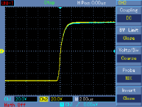
Vladimir, how does this story look if you limit the input signal to say 20kHz or 25kHz? See attached. Start with a 'exaggerated 10uS rise time input, 1st order roll off at 25kHz to simulate audio signal.
Put that in your amp, and look at the ringing.
I won't even get started why you think a well-designed audio amp should have 5uS settling time...
jan
Attachments
There is an original thread about the Blowtorch. The original topic had been closed and moved here, to be transformed in a boxing theater. The ring is used by several audio designers and other electronic engineers, but not reserved to professionals.Knock, knock, knock…
Hello, is there anybody here?
Is this thread about John Curl's Blowtorch preamplifier?
Feel free to enter in the ring any time. Nobody had been killed till now, but several seriously injured, including John, the titleholder.
Notice, it is free entrance, opened 24/24 and the show turn circles non-stop.
In red, the 'objectivists', in black, the 'audiophiles', in the middle, J.C.
Last edited:
Yes Jan, these stories here are funny, funny and nothing but funny. Please let me attach a step response of the 250W/4ohm power amplifier, with the evil Global Negative Feedback. 106Vp-p voltage swing.
Attachments
Last edited:
I'm stuck with a little stupid problem, you know how it is.
it is absolutly out of topic, but there is the place where i have more luck to find clever people")
U3 sum double full wave rectifiers and amplify the rectified signal. It works fine, but the + & - signal balance is affected by he RV value, so R need to be finely tuned for each value of RV. (giving R the same value than RV, between 10K and 1Mohm)
Any idea to get rid of this without adding an other OPA ?
it is absolutly out of topic, but there is the place where i have more luck to find clever people
U3 sum double full wave rectifiers and amplify the rectified signal. It works fine, but the + & - signal balance is affected by he RV value, so R need to be finely tuned for each value of RV. (giving R the same value than RV, between 10K and 1Mohm)
Any idea to get rid of this without adding an other OPA ?
Attachments
Last edited:
- Status
- Not open for further replies.
- Home
- Member Areas
- The Lounge
- John Curl's Blowtorch preamplifier part II