Richard, it seems damn right !added bridging cap seems to dynamically push rail with lower loading to higher output voltage (adding ripple)..
If you consider the cap across + &- as infinite, the voltage between the + & - will stay the same. Any current on the + rail will tend its voltage to decrease , and the cap force the -V to go the same sens, means more -V.
Seems to do the contrary than what we try to do, keep rails symmetrical .
I was tired, yesterday night, but some red light was warning in my head in the reptilian areaDefinitely. It only transfers ripple from one rail to the other one.
It does more than that. And, if it is designed so the ripple is out of phase, it too will cancel.Definitely. It only transfers ripple from one rail to the other one
Last edited:
Richard, it seems damn right !
If you consider the cap across + &- as infinite, the voltage between the + & - will stay the same. Any current on the + rail will tend its voltage to decrease , and the cap force the -V to go the same sens, means more -V.
Seems to do the contrary than what we try to do, keep rails symmetrical .
Simple and effective. It works well in practice and has been used successfully in many circuits. Especially power amps.
Better still... especially for low power equipment.... I would like to see more designs here of high performance Tracking Regulators brought into high-end mainstream use. This sort of thing helps reduce one of the negatives in using current fb amps. Its easy to try it at home in your own equipment.
Thx-RNMarsh
Last edited:
It does more than that. And, if it is designed so the ripple is out of phase, it too will cancel.
[PMA - I see you were refering to Christophe's circuit implimentation... OK]
We all pretend the contrary, Richard. Please re-read our posts. This cap between +&- rails ADDS riple in phase, while we wanted it in opposition. And i see no way we can play with values able to add 180° phase turn as the load is constantly changing, by definition, so cannot be defined as a passive element. Did i miss something ?Simple and effective... It does more than that.
The goal is nice, but the only solution i can imagine is active or something with coupled coils in serial..
Last edited:
Assumptions -- Looking deeper
From the amplifier's perspective --- What is important in a power supply is not the absolute voltage of the rails. Making rails be precisely the same isnt important. They just need to be the SAME voltage at all load levels esp with asymetrical waveforms (music)/currents.
Making voltage regs be brutally stead-fast is one way to avoid any differential between rails.... but it really is a brute force approach to what it is the amplifier responds to.
Many people look at simple circuits and think they are not sophisticated. JC's circuits and implimentations are a case in point. But actually they are deceptively refined and it isnt always obvious. Ditto Scotts designs. Of course, he hasnt told you most of the not so obvious stuff in its implimentation.
For example, in the future, some might see a ps 'balancing' cap across the rails and assume it just does this or that for the power supply. Not thinking it got there due to the amplifier's topology being used. Or, substitute a different reg than the Tracking reg being used.
Thx-RNMarsh
Last edited:
Richard,
In the thread by Gootee, Power Supply Resevoir Size, this subject was touched on by a few there. Any chance since you are one of the capacitor guru's in this regards that you could go into a bit of detail on this? Perhaps even a simple circuit design showing the placement of the caps and how you would determine the correct values for a power supply side application? Just asking....
In the thread by Gootee, Power Supply Resevoir Size, this subject was touched on by a few there. Any chance since you are one of the capacitor guru's in this regards that you could go into a bit of detail on this? Perhaps even a simple circuit design showing the placement of the caps and how you would determine the correct values for a power supply side application? Just asking....
We all pretend the contrary, Richard. Please re-read our posts. This cap between +&- rails ADDS riple in phase, while we wanted it in opposition. And i see no way we can play with values able to add 180° phase turn as the load is constantly changing, by definition, so cannot be defined as a passive element. Did i miss something ?
The goal is nice, but the only solution i can imagine is active or something with coupled coils in serial..
Well you can have more time to think about how to do it. A dual tracking reg is a good alternative for the goal. I see many series, shunt and series-shunt combo's but not Tracking each other. not much effort to do so. Thx-RNMarsh
Richard,
In the thread by Gootee, Power Supply Resevoir Size, this subject was touched on by a few there. Any chance since you are one of the capacitor guru's in this regards that you could go into a bit of detail on this? Perhaps even a simple circuit design showing the placement of the caps and how you would determine the correct values for a power supply side application? Just asking....
Afraid not now.... but I hope you see the issue of how amplifier's low PSRR can be helped with a supply that tracks. Go there and you will find many circuits that exist and work with those and refine them. Look for dual Tracking Regulators.
I just want to lead one to the trough....
Thx- RNMarsh
Last edited:
Afraid not now.... but I hope you see the issue of how amplifier's low PSRR can be helped with a supply that tracks. Go there and you will find many circuits that exist and work with those and refine them. Look for dual Tracking Regulators.
I just want to lead one to the trough....
Thx- RNMarsh
I think dual tracking regulators like this LT3692 - Monolithic Dual Tracking 3.5A Step-Down Switching Regulator - Linear Technology have very little to do with putting a cap over + and - in addition to the ones to ground.
Without further explanation of what you mean to say, I can only agree with PM's conclusion.
In addition, I understand your point about ripple on + and - potentially balancing out, but the major ripple on a rail usually is load induced (if only because of inductance), and this is assymetrical, so ripple will be amplified.
By linking the two rails, what I see happening is that your ground gets pushed around with respect to the rails. So, in a fully balanced circuit where nothing is referred to ground, this might work. Not very practical though.
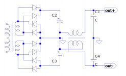
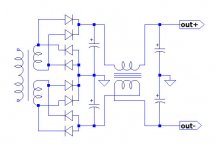
This could be the job ?:
yes that helps with Diff-Mode of HF/RF But it doesnt do the duty of keeping the + and the - rail voltages the same value.... which is needed for amps with low PSR.
It would work on your series C- multiplier circuit if the 'balancing' C was on its outputs rather than input.
-RNM
Last edited:
Concepts -
Challenges are great. You guys are getting Way off track, again. It has nothing to do with ripple cancelling. Not for that purpose. You guys figured out that DM noise on the supply is an issue for amps with low PSR.. And it can be cancelled by a number of means at the PS level.... A small value cap bridge can do that. But the issue is to also keep both rails at the same voltage even if that voltage's absolute level changes. That's your challenge and why it is needed.
An app might assume a current feedback power amp without regulated output stage. What would you do to help the amplifier via the PS?
Thx-RNMarsh
I think dual tracking regulators like this LT3692 - Monolithic Dual Tracking 3.5A Step-Down Switching Regulator - Linear Technology have very little to do with putting a cap over + and - in addition to the ones to ground.
Without further explanation of what you mean to say, I can only agree with PM's conclusion.
In addition, I understand your point about ripple on + and - potentially balancing out, but the major ripple on a rail usually is load induced (if only because of inductance), and this is assymetrical, so ripple will be amplified.
By linking the two rails, what I see happening is that your ground gets pushed around with respect to the rails. So, in a fully balanced circuit where nothing is referred to ground, this might work. Not very practical though.
Challenges are great. You guys are getting Way off track, again. It has nothing to do with ripple cancelling. Not for that purpose. You guys figured out that DM noise on the supply is an issue for amps with low PSR.. And it can be cancelled by a number of means at the PS level.... A small value cap bridge can do that. But the issue is to also keep both rails at the same voltage even if that voltage's absolute level changes. That's your challenge and why it is needed.
An app might assume a current feedback power amp without regulated output stage. What would you do to help the amplifier via the PS?
Thx-RNMarsh
Last edited:
I think you misunderstood. Your cap ADD ripple (means not the same voltage), as the two sides will follow the same ripple the same sens.yes that helps with Diff-Mode of HF/RF But it doesnt do the duty of keeping the + and the - rail voltages the same value.... which is needed for amps with low PSR.
Let say the boths sides are 10V, and ripple -1V on the positive side. it makes 9v on the positive side. Your cap try to add the same -1V to the negative rail (the cap try to keep the same voltage): -1-10= -11V.
+9 V, -11V: the differential ripple had doubled.
In my last schematic, any ripple on one side will try to mirror with opposite phase on the other side of the psu. So, the both sides tend to stay symetrical, what we want.
[10-1] & [-10+1] = + 9 & -9V
How to be more clear ?
PS: i asked what means the DM acronym, had no answer. Differential mode ?
Last edited:
I think you misunderstood. Your cap ADD ripple (means not the same voltage), as the two sides will follow the same ripple the same sens.
Let say the boths sides are 10V, and ripple -1V on the positive side. it makes 9v on the positive side. Your cap try to add the same -1V to the negative rail (the cap try to keep the same voltage): -1-10= -11V.
+9 V, -11V: the differential ripple had doubled.
In my last schematic, any ripple on one side will try to mirror with opposite phase on the other side of the psu. So, the both sides tend to stay symetrical, what we want.
[10-1] & [-10+1] = + 9 & -9V
How to be more clear ?
PS: i asked what means the DM acronym, had no answer. Differential mode ?
DM = Differential-Mode. Yes, your idea works with 1:1 transformer action to cancel DM noise. I use it in ac power line filters as well as combined with CM noise filters. It is fine way to help amp circuit's with low PSR. Note though --- dc thru the core would reduce the L a lot.
Thx-RNMarsh
Last edited:
Yes I am. At least for low-medium current apps.Christophe,
I may be wrong here but I think that what Richard is pointing at is a regulated tracking power supply.
- Status
- Not open for further replies.
- Home
- Member Areas
- The Lounge
- John Curl's Blowtorch preamplifier part II