You always said that, but never why ? Did-you ever tried some CFB OPA like AD844 ?I happen to prefer the AD825 for my line amps. I am using it in new designs.
You will have nothing to complain about high order harmonics.
Last edited:
Thanks again, Electroj, for putting up the article that you put up here. I first misunderstood what you wanted from me. What you want is the rest of the article, rather than a second part to the article. I will dig around, it is here, someplace, but I have to individually scan it, so it might take some time. .....
Thanks, John. Yes, I wanted to see a second part of Antler's article "Effect of Surface Contamination on Electric Contact Perfomance".
I checked Amazon - the above mentioned book by Ragnar Holm is still available, but it has it's price tag. I'm not deeply into contacts and won't be buying it tomorrow, but I did put it on my "books to buy" list. Thank you, Richard, for pointing to it.
I just don't have any AD844 devices to play with. Scott forgot to sample me. '-)
You never asked, a little late now.
Irrelevant- what's the actual impedance? Sheesh. And the references don't actually say that, but don't let that get in the way.
Take a look at Fig 4.9 in Morgan Jones's book- he actually measured a cheap 10,000uF aluminum cap. The impedance at 6kHz was a whole 2 milliohms. Self resonance frequency is 15kHz, but the impedance at 100kHz is 8 milliohms. My bridge isn't quite as good as his, but I was able to confirm that the ESL of the cheap 10,000uF/35V (I didn't have any 25V units on hand) aluminum caps in my stock is about 10nH.
You indeed did the calculation, plugging in incorrect numbers and ignoring scaling factors. I went through that pretty thoroughly so that anyone could follow, not going to bother to do so again. There's a reason that 797 based preamps are dead quiet. Even if you dispute the widely-known-accurate PSUD2 sim, you're taking the difference between -250dB and -244dB noise. Seriously?
The rodeo clown act for John's benefit gets old. His claims are still false no matter how much dust you try to kick up.
edit: Here's my "work" to show the actual ripple. Plugging in values for components I had on hand, I find that my 120mV estimate was indeed too high- it's ~70mV p-p. Makes the concern even more ridiculous. PSUD2 is a "known-good" sim- I'm not a big believer in sim software, but again and again, it's given me (and thousands of other users) accurate results.
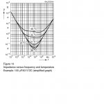
Now I see the source of confusion. The Equivalent Series Inductance (ESL) of most electrolytic capacitors is measured at .5 Volts AC RMS 100 or 120 Hz. Not at higher frequencies for data sheet use, as they are usually considered inappropriate for such use, unless specially constructed. The Equivalent Series Resistance (ESR) is the part of the equation that is considered to vary with applied DC voltage, frequency and temperature. Note these are modeling values not the small signal ones.
I have attached the graph showing how the attenuation varies with frequency and temperature for a 100 uF capacitor. I think it clearly shows the limits of such a capacitor. Note the dramatic change with temperature. real inductors don't do this.
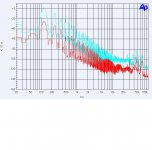
Now when you try to scale things such as this there is often a square or square root involve. However as shown in the second measurement the filtering effect of a .01F capacitor does begin to limit in the audio band. It shows the filtering comparison of a 470 uf and a .01F. The 470uF does not show the issue in the audio band. That is why many use equal value parallel capacitors to make the total filter capacitance. These are also augmented with smaller capacitors to extend the filtering range.
You are welcome to do your calculations showing - infinity or -165 or -220 or whatever you want. When you measure a real circuit you will be hard pressed to get -150 (all re 1 V RMS).
Now my listing of noise values is also based on measured performance. Interestingly Bonsai seems to have the same numbers.
Now that you broke down and actually measured the ripple (since I presume you wanted to disprove the calculations based on the definition of capacitance.) I think you will find when you measure electrolytic capacitors for value you will almost never find one 20% low as in the typical specification limit. Some also specify 80% high and you might actually see that. But most measure about 20% high when new. That is because storage conditions, time and even soldering them into a circuit will cause a decrease in value. Some of this is of course regained when placed back under voltage.
ES
Attachments
Last edited:
It's OK, Scott. You were once very generous with samples to me, more than just about anyone else, except possibly Walt Jung.
I would not have used the AD844 in any case, because my designs are usually based on complementary jfets, but I know that Charles Hansen of Ayre, used the AD844 for a time.
I would not have used the AD844 in any case, because my designs are usually based on complementary jfets, but I know that Charles Hansen of Ayre, used the AD844 for a time.
Just order them on line ? It is less expensive than a BlowtorchI just don't have any AD844 devices to play with. Scott forgot to sample me. '-)
")
I would be curious to have your feedback.
I would not have used the AD844 in any case, because my designs are usually based on complementary jfets,
Nor AD825 is.
Just order them on line ? It is less expensive than a Blowtorch
I would be curious to have your feedback.
He wouldn't. "Pride and Prejudice"
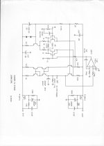
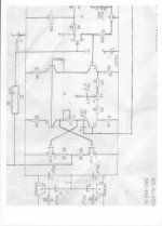
If anyone here would look at the schematics that I have put forth on this thread in the last year or so, they would discover a number of designs that use a dual jfet input and bipolar transistors for the rest of the design, unless I can also use mosfets instead. I have been designing this way since the Levinson JC-2 phono stage. It is not my 'best' effort, but it is easy to do, and works pretty well.
How-can-you know if you don't try ?which is the best that I can get from IC's.
And what about Jfet input if you don't need high Z ?
Last edited:
John, it is very strange to see-you so stuck on your definitive convictions. All the real progress i had made in my audio knowledge was always due to extensive questioning and 180°turns.
Listening to (valuable) people with opposite point of view.
Of course, we all tend to make definitive laws of thinks witch 'works'( in a given environment)... until we discover it was not a so 'general' or 'absolute' law.
"What were onces habits are now vices" would had say the Doobies, paths that lead to paradise are multiple and it is fun to walk in new landscapes.
- Status
- Not open for further replies.
- Home
- Member Areas
- The Lounge
- John Curl's Blowtorch preamplifier part II