John, i was curious to know the Ampex recorders you had designed some audio parts in. Would-you be nice enough to satisfy my curiosity ?
AD: SSM2141, SSM2142,
or better: TI: DRV134, DRV135
THAT:1606, 1646 ...etc
Why bother ?Talk about 'babying' the 797. Now, all we have to add is a high quality inverter to give us balanced output. Maybe another AD811.
I bet the combination will measure pretty darn well.
AD: SSM2141, SSM2142,
or better: TI: DRV134, DRV135
THAT:1606, 1646 ...etc
Last edited:
The values in Table 6 or Table 8 of the datasheet would be a good starting point- and likely a good ending point.
There's also likely a lot of other candidates in the IC world, I chose the 797 for illustration because I have some and I'm familiar with them.
So, where's that all-important 7th and 9th harmonic distortion data? Lower than -200dB is not good enough?
There's also likely a lot of other candidates in the IC world, I chose the 797 for illustration because I have some and I'm familiar with them.
So, where's that all-important 7th and 9th harmonic distortion data? Lower than -200dB is not good enough?
I worked with the AG-440, MM1000, and the AG500, and 600.
45 years ago, I was testing the AG-440 electronics virtually every day, with an HP wave-analyzer, sometimes for distortion, sometimes for noise.
At the same time I developed the first phase locked capstan servo for the AG-440 back in 1968.
45 years ago, I was testing the AG-440 electronics virtually every day, with an HP wave-analyzer, sometimes for distortion, sometimes for noise.
At the same time I developed the first phase locked capstan servo for the AG-440 back in 1968.
I designed the signal recording head amplifier for my 16/35mm machines. As i wanted a max headroom, and the habit was to set a CS with a serial resistance in the head path, i used a (shielded) spare recording head in feedback loop instead. With incredibly good results.
Then: For 2'nd harmonic, estimate that its value drops directly with voltage level.
For 3'rd harmonic, estimate that its value drops directly with the SQUARE of the voltage level.
For 4'th harmonic, estimate that it drops to the CUBE of the voltage level.
Etc, etc.
Now what about 7th harmonic? It should drop as the 6th power, which implies that if you drop the voltage level in 1/2, then the 7th harmonic should drop by a factor of 64.
.
Really, I think you need to review the concept of second and third order intercept.
OK, time for clarification: 7th harmonic is one of the most significant harmonics that the ear can detect with music. It is fairly easy to generate, as well, with crossover distortion and diode nonlinearities in electronic circuitry.
A dozen years ago, my main assumption was that if I could reduce 7th harmonic at listening levels to, let's say: -120dB or one part in 1 million, then the circuitry should be OK. I used this standard to compare my Parasound power amps, testing them invariably at the Xover region between Class A and Class A-B, where the transfer function is the weakest. This is NOT a classical Class A situation, and like IC's, can suffer Xover distortion, of some magnitude, during the transition between Class A and Class B.
Now, this transition may happen between 1W and 30W on my power amps, but where does it come in from a typical IC?
Let us use the approximation that the output stage is biased at 1/2ma. That means that the A-B transition will happen after about 1ma peak output, either + or - .
What voltage level does that translate to?
Well if we did what SY directs, then we would have a 10K feedback resistor with a 1.1K to ground, and a 50K amplifier load. This would be an effective load of about 10K, so 1ma and 10K load, gives us 10V peak output. Pretty good, but is it practical? No, because in the case of the AD797, the noise has risen 5 times over the design's inherent capability, due to the 1K of feedback resistance of 4nV/rt Hz. So, IF you want to use the capability of the AD797 to its advantage, we MUST reduce the feedback resistor. I recommend 50 ohms, that only throws away about 3dB from the best noise possible. Now for a gain of 10, what is the main feedback resistor value? It is 450 ohms, giving the op amp a 500 ohm load. Too much? What to do? How about 1500 ohms for the output, and 165 ohms for the feedback resistor? Not bad, BUT you could not get any more than 1.6V PEAK from the IC, before it went into Class A-B transition. Now, is that a problem? To me, yes, to you, perhaps not.
Well the only thing I get from this is that feedback resistors determine noise performance, not the 797.
Scott must be happy for you to endorse his baby like that!
jan
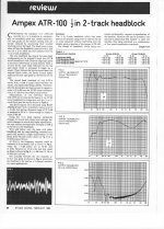
The Ampex ATR1x0 machines were very special. It used a servo-controlled, direct-drive-capstan tape transport, which allowed the tape speed and tension to be continuously monitored by a servo relay, without capstan and counter-capstan. The capstan was replaced by a free turning weel, in contact with the tape, measuring the speed. The purpose was to reduce wow and flutter.
Working very well, while boring to set the tape: needed adhesive to stick the beginning of the tape, and more free turns of the tape on the receiving weel than habit.
The fast rewind process was incredible fast, affraying, while perfectly monitored; the tape was slowed down in a very controlled and smooth way to the chosen locator's point. A science fiction transport.
They too used magnetic heads made of ferrite, to avoid wear.
This was a VERY bad idea, as the ferrite crumbled in the gap, and, if the head was not wearing with tape friction,some heads were often destroyed very fast and in an non predictable way.
When you had the luck to get good heads, you had what was probably the best analog recording machine ever made.
Last edited:
Until you bought your PC with a good sound cardWhen you had the luck to get good heads, you had what was probably the best analog recording machine ever made.
")
You haven't shown any results whatever, much less a method. Nothing. Nada. Zip. Bupkis. Rien. Nichts.
Did JC ever admitted wrong? No, so I would think harrasing him is nothing but a waste of time. Minus, of course, the entertaining value of ruffling the feathers of a well known audio designer.
I don't want to be wrong, but I will stand corrected WHEN you give me something to correct.
As far as the ATR100 is concerned, I preferred Studer transports, and my own electronics. That is what I did for Mobile Fidelity and Wilson Audio.
Some of the systems concepts are very good in the ATR100. I used the record system concept, first shown by Allister Heaslett, the major designer of the ATR100, to get optimum phase response.
Last edited:
OK, then let's do the math without the need for a codex. If I have a bare bones supply (cheap 10,000uF/25V cap, no fancy choke or extra RC) and a whole pile of circuitry (let's say 100mA of draw), raw supply ripple is 120mV. At your chosen 3kHz, harmonics are -40dB wrt 120mV. A 7815 will knock that down another 55dB (and a 317 with cap bypass will be about a hundred times better, but let's stick with a 7815). 797 knocks that down another 95dB. So there's our line stage. The power amp is likely to have 26dB of gain. Overall, then, we deliver a signal -164dB down from 120mV at the speaker terminals (something less than a nanovolt). I haven't taken the math further, but I bet that's pushing the thermal noise of the voice coil.
SY,
CV=q or C dv/dt + Vdc/dt =i dc/dt is close enough to zero we normally neglect the term so dv = i dt / C or .1 x 1/120 x 1/.1 = 83 mV ripple. (100 mV in the UK.)
So at 3kHz we would expect 833 uV. At 3000 Hz. you don't get 55 dB of reduction you are lucky to get 30 so we are now at 26 uV. Use the AD797 at -90 (Negative rail) and you get your less than a nanovolt or .82nV. Now add the preamp gain of 60 db to see 822 nV even if you run your power amp at 0 db that would put the noise at -131 dBW at 3 kHz.
Now lets run those noise figures for each octave, weight them and add up the results!
Freq.....Harmonic Level...Sensitivity...Regulator...Noise
60...........-6....................-55.............55......1.32069E-07
120...........0....................-30.............55......4.68599E-06
240..........-6....................-15.............52......1.86553E-05
480.........-12......................0.............49......7.42679E-05
960.........-18......................0.............46......5.25777E-05
1920........-24.....................6.............43......7.42679E-05
3840........-30.....................6.............40......5.25777E-05
7680........-36....................-5.............37......1.04906E-05
15360......-42....................-6.............34......6.61914E-06
30720......-48....................-6.............31......4.68599E-06
61440......-54....................-7.............28......2.95666E-06
122880....-60.....................-8.............25......1.86553E-06
................................................................0.000303782 Volts
Probably why most folks don't use the 7915!
Now the other issue is the actual regulator noise will increase that a bit. Or in practice don't oversize you filter capacitor because at some point it is not the ripple and harmonics it is the self noise. Also a calculable number.
Last edited:
SY,
CV=q or C dv/dt + Vdc/dt =i dc/dt is close enough to zero we normally neglect the term so dv = i dt / C or .1 x 1/120 x 1/.1 = 83 mV ripple. (100 mV in the UK.)
So at 3kHz we would expect 833 uV. At 3000 Hz. you don't get 55 dB of reduction you are lucky to get 30 so we are now at 26 uV. Use the AD797 at -90 (Negative rail) and you get your less than a nanovolt or .82nV. Now add the preamp gain of 60 db to see 822 nV even if you run your power amp at 0 db that would put the noise at -131 dBW at 3 kHz.
Now lets run those noise figures for each octave, weight them and add up the results!
Freq.....Harmonic Level...Sensitivity...Regulator...Noise
60...........-6....................-55.............55......1.32069E-07
120...........0....................-30.............55......4.68599E-06
240..........-6....................-15.............52......1.86553E-05
480.........-12......................0.............49......7.42679E-05
960.........-18......................0.............46......5.25777E-05
1920........-24.....................6.............43......7.42679E-05
3840........-30.....................6.............40......5.25777E-05
7680........-36....................-5.............37......1.04906E-05
15360......-42....................-6.............34......6.61914E-06
30720......-48....................-6.............31......4.68599E-06
61440......-54....................-7.............28......2.95666E-06
122880....-60.....................-8.............25......1.86553E-06
................................................................0.000303782 Volts
Probably why most folks don't use the 7915!
Now the other issue is the actual regulator noise will decrease that a bit. Or in practice don't oversize you filter capacitor because at some point it is not the ripple and harmonics it is the self noise. Also a calculable number.
a) I don't know what you are talking about within the first paragraph.
b) Fig. 31 shows 75dB of rejection @3KHz, far lower than the 30dB you mentioned.
c) 60dB gain for a line preamp doesn't make any sense.
d) I have no idea what the last paragraph table means and how you used it to prove your point.
Figure 31 is a 7805 at 1/2A. Let me know what you measure on a 7915!
You are jealous because you don't found the path to the game's registration.Minus, of course, the entertaining value of ruffling the feathers of a well known audio designer.
I won 10 points !As far as the ATR100 is concerned, I preferred Studer transports, and my own electronics.
Figure 31 is a 7805 at 1/2A. Let me know what you measure on a 7915!
Oh, sorry, so you shifted the discussion from the 7815 here to a 7915, known as having a much worse frequency response. Good to know.
Still, the rest doesn't make much sense. But the 7915 has it's own noise of 175uV in 100KHz BW, much larger than those 26uV coming from that so-called "ripple" @3KHz. Plus that we have something called "decoupling".
You would pull anything out of thin air to make a point, isn't it?
- Status
- Not open for further replies.
- Home
- Member Areas
- The Lounge
- John Curl's Blowtorch preamplifier part II