Well now that our opinions are out in the open, let us go forth and exchange understanding.
Understanding of what?
Well... I understand that the more I know the more I understand that I know nothing...
Your turn!
")
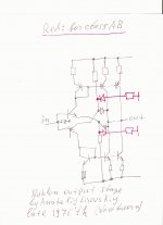
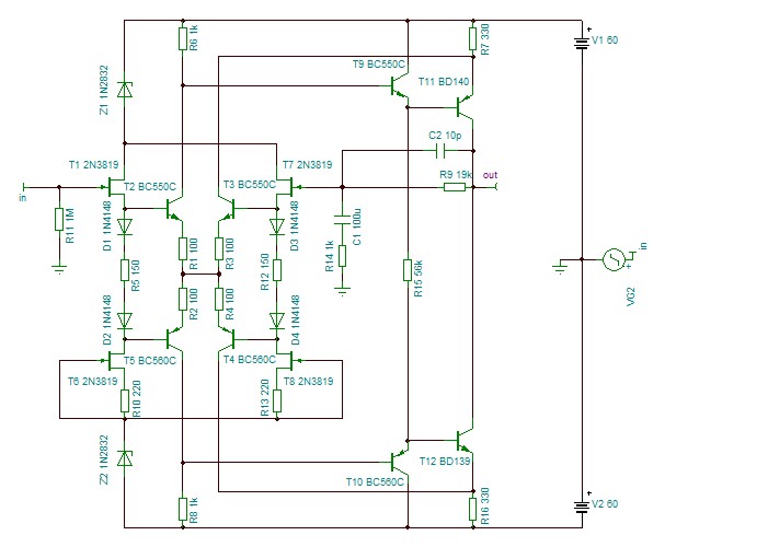
Nuklon
I mean this output stage, John. I was bright kid then...
As you may see, it is a complementary symmetrical opamp. LTPs consist of one trasistor and 1 diode, because:
1) unity gain, no resistors in feedback, no need for feedback current amplification,
2) if to short output reverse biased b-e junctions would go to avalance break-down.
Also, long tails intentionally shorted, i.e. use resistors instead of current sources, so current in tails follows signal, and max output current depends on signal.
Currents are set by resistors such a way so iddle current equals to half of peak current. I.e. it is an economical class A output stage
No need for additional protection of output transistors, because if to decrease load resistance it smoothly shifts from voltage
follower mode to current output mode.
Optional tail-shorting networks of resistors and diodes in series allow to operate it in class AB mode. It has advantage over conventional class AB mode: no cross-over transistor switching off, instead diode switching that is fast and smooth.
I don't understand why people continue using junk when such solution is available in public domain.
Attachments
Last edited:
Looks good, Wavebourn.
Sounds too. And fter I modified lots of amps with damaged output transformers and ICs nobody came back to repair.
What have we covered so far of the potential advantages with the complementary differential jfet input stage?
1. It is self biasing, not needing extra current sources.
2. It can have a peak current drive much higher than 2Id, that is one of the fundamental limits to slew rate limiting, and this 'advantage' can make many circuits faster.
3. The transfer function of the jfet is more linear than the bipolar transistor (without emitter resistor degeneration), and components of distortion are lower order in general.
4. With low noise jfets, this circuit can be VERY quiet, and it will NOT get noisier with higher Z drive impedances, such as a potentiometer.
5. There is virtually no input current to worry about.
6. The fet input is more immune to RF detection because there is no working diode at the input.
7. And perhaps more, but I am working on my first cup of coffee, and can't think of any.
'-)
Last edited:
John,
I agree with your points, but no one uses BJT's without degeneration now days. Sure degen will incur some noise penalty. Secondly, it's difficult to run a JFET input stage like this without a servo. Even using blocking cap still gives drift problems with the JFET.
That said, I think the circuit is very elegant. it is a pity matched pairs are getting more difficult to source.
Now what are some of the disadvantages using the complementary different jfet input stage?
1. It is not compatible with IC production.
2. It is a real current hog.
3. It takes a lot of parts.
4. Jfets have recently become difficult to get at the moment, just like tubes did, perhaps 20 years ago.
5. I am sure there are more, and interested parties will tell me what they are.
Well, what do we do about it? For complete novices and people located in isolated locations across the world, it might not be practical to use a complementary differential jfet input stage, just like it would be impractical to design a car engine that needs 120 octane gas (aviation fuel) to run, for use in the USA. It might be just too difficult to source the devices.
Linear integrated systems has developed complementary parts that would work, like the j113-175 combination, and these are available, today, but the really good part the LSK74 is still not released for general sale, but someday soon, I hope.
John,
I agree with your points, but no one uses BJT's without degeneration now days. Sure degen will incur some noise penalty.
And of course one can tie the emitters together with an inductor to bypass the degeneration resistors and their audio-band noise. Treacherous if not done properly, but effective.
Having said that, I love JFETs.
Brad
"Mind the bandgap" must be someone who has visited London. On certain Tube platforms, generally the few which are on a sharp curve, a PA announcement says "Mind the gap". The gap can be quite large in the centre of a carriage (car - for my American readers?).
The most hilarious of all: The clothing stores at Heathrow, where you can buy a bikini for the missus, and on the front of the bikini bottom, it has the tube symbol, 'Mind The Gap'.
What have we covered so far of the potential advantages with the complementary differential jfet input stage?
1. It is self biasing, not needing extra current sources.
2. It can have a peak current drive much higher than 2Id, that is one of the fundamental limits to slew rate limiting, and this 'advantage' can make many circuits faster.
3. The transfer function of the jfet is more linear than the bipolar transistor (without emitter resistor degeneration), and components of distortion are lower order in general.
4. With low noise jfets, this circuit can be VERY quiet, and it will NOT get noisier with higher Z drive impedances, such as a potentiometer.
5. There is virtually no input current to worry about.
6. The fet input is more immune to RF detection because there is no working diode at the input.
7. And perhaps more, but I am working on my first cup of coffee, and can't think of any.
'-)
I would add:
High Id (compared to BJT) plus peak current available widens a choice of devices for the second stage.
Best,
I would add:
High Id (compared to BJT) plus peak current available widens a choice of devices for the second stage.
Best,
I don't believe FETs have an advantage over BJTs regarding Id or Ic.
BJTs can be driven to arbitrarily large currents to charge parasitic or real capacitances to avoid slew rate limiting.
jan
Oh sure they do, it is possible to run up to 15ma with jfets. Try that with bipolars, and you get too much self noise, and a lowish input Z.
I should point out that I have designed with this circuit since 1968, when bipolar transistors were the only realistic choice. I made dozens of different designs, both amps and preamps when working at Ampex and Alembic, using matched bipolar pairs between the years of 1968-1971, and I found that 2ma was pretty much the maximum Id for each input bipolar device.
While, with some designs, even today, I may run at 2ma with jfets, my PEAK drive current is much, much more than the 4ma that bipolars would be normally limited to.
With other designs, such as the CTC Blowtorch, I might run up to 15ma per jfet device, without any noise penalty due to extra noise generation in the input devices.
John,
I did some thinking about this and came up with this...
I personally rejected it for use.
BTW, I cannot really claim that one, it's earlyish lower end Accuphase... Still, I can see uses...
Ciao T
Well, what do we do about it? For complete novices and people located in isolated locations across the world, it might not be practical to use a complementary differential jfet input stage, just like it would be impractical to design a car engine that needs 120 octane gas (aviation fuel) to run, for use in the USA. It might be just too difficult to source the devices.
I did some thinking about this and came up with this...
I personally rejected it for use.
BTW, I cannot really claim that one, it's earlyish lower end Accuphase... Still, I can see uses...
Ciao T
Attachments
Oh sure they do, it is possible to run up to 15ma with jfets. Try that with bipolars, and you get too much self noise, and a lowish input Z.
I've seen bi-polar MC preamps with 25mA/side.
Scott, it is obvious that you have not lived with a Quan-Tech noise analyzer on a daily basis for most of your life. You would find that for a SPECIFIC 'low noise' device that it is impractical to go above 10ma, and even then, ONLY for VERY LOW impedance drive, below 100 ohms. You are giving INFO that will only confuse, rather than give understanding. I am NOT designing MC pre-preamps here, and I would hope that you would realize that. Later, I might give an example of what happens IF you design with a bipolar input and run very high input currents, the 'trade-offs' so to speak, but not now.
T, further consideration of the circuit that you just put up shows a true engineer's understanding of the problems, and a practical solution that could have been effected even in the middle 1960's without too much of a problem, since the 2N3819 was available even then.
John,
I agree, complexity is much up. But it allows very simple, cheap and generic parts to be used, which was my aim.
I suspect for the price of a matched Quad of 2SK170/2SJ74 we can buy a lot of 2SC2240/2SA970 and 2N3819 or similar...
Performace, I think it could be broadly comparable, if time is taken for optimisation...
Thank you for the flowers and yes, I agree.
It is truly a pitty that in the year 2012 we have to resort to such circuitry. I would have expected some form of monolithic J-Fet quads in big 12-Pin TO Metal Can enclosures instead of we are getting, just goes to show WTFDIK...
It sorely lacks the elegance of your complementary J-Fet solution and as it so happens, I do have hundreds of matched K170/J74 pairs (marked to 0.01mA Idss per pair) around, so I do not have to use it...
Ciao T
It would work, but at what 'price' in complexity and performance?
I agree, complexity is much up. But it allows very simple, cheap and generic parts to be used, which was my aim.
I suspect for the price of a matched Quad of 2SK170/2SJ74 we can buy a lot of 2SC2240/2SA970 and 2N3819 or similar...
Performace, I think it could be broadly comparable, if time is taken for optimisation...
T, further consideration of the circuit that you just put up shows a true engineer's understanding of the problems, and a practical solution that could have been effected even in the middle 1960's without too much of a problem, since the 2N3819 was available even then.
Thank you for the flowers and yes, I agree.
It is truly a pitty that in the year 2012 we have to resort to such circuitry. I would have expected some form of monolithic J-Fet quads in big 12-Pin TO Metal Can enclosures instead of we are getting, just goes to show WTFDIK...
It sorely lacks the elegance of your complementary J-Fet solution and as it so happens, I do have hundreds of matched K170/J74 pairs (marked to 0.01mA Idss per pair) around, so I do not have to use it...
Ciao T
- Status
- Not open for further replies.
- Home
- Member Areas
- The Lounge
- John Curl's Blowtorch preamplifier part II