Well SY,
Today gear goes above 30 Mhz and leaded bypass capacitors are rarely used.
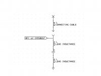
This is the circuit theory representation of what I am talking about. The top X on the circuit is undetermined. It can be another piece of audio gear or even an open cable.
ES
Today gear goes above 30 Mhz and leaded bypass capacitors are rarely used.
This is the circuit theory representation of what I am talking about. The top X on the circuit is undetermined. It can be another piece of audio gear or even an open cable.
ES
Attachments
That was your worry, not mine; I was just putting some numbers to it to try to figure out what you're on about. Bypassing the input plug to the chassis with a small ceramic cap with reasonably short leads is a standard method, and it's standard because it's effective. I think my Collins S-Line even used the same method. I put some numbers to your example, and that led to less physically reasonable examples.
Some years ago, I have made some measurements on decouplers in a 50 Ohm system.
< http://www.hoffmann-hochfrequenz.de/downloads/experiments_with_decoupling_capacitors.pdf >
A Collins S-line, that was the Holy Grail when I was a teenie
")
Gerhard, DK4XP
A Collins S-line, that was the Holy Grail when I was a teenie
Took a lot of summer work hours as a teen to get the money for that, even second-hand. As someone who built all his own gear before that, it killed me to admit how much better the Collins stuff was.
(ex-WA3KHZ)
Yes, if you use an unshielded cable (that's what you show here), you'll have all sorts of interference and noise pickup. Most people use shielded cable. And as a simple calculation shows, a small bypass cap works well up into VHF.
We are talking about the RF on the shield!
We are talking about the RF on the shield!
No, we are talking about a solid ground on the shield.
We are talking about the RF on the shield!
That's the whole point of bypassing at the input.
No, we are talking about a solid ground on the shield.
What about installing a .01uf cap between the insulated RCA body and the case? This should bypass RF to ground. Not a perfect RF answer, but better than not using the cap.
The start of this was bypassing an RCA connector mounted in an insulated bushing on a metal panel to avoid grounding issues a bypass capacitor is added from the shell to the chassis at the point of entry. We are not talking about RFI removal from the signal carrying conductor.
In the case under discussion it is the RF leakage on the shield that is not decoupled at the chassis entry that can cause problems farther along the circuitry.
Your nice work is of the ability of a capacitor to perform under the best conditions for such a component.
If you add the inductance of the shield as I showed to the limits of a real capacitor you get at some frequencies essentially a tuned antenna! This signal is then coupled into the circuits ground plane and can cause problems.
A leaded ceramic capacitor at the RCA jacks point of entry connected to the chassis is of limited use to lower frequencies. This is not the same case of bypassing a noise source.
The issues are the source: Which in this case is not a local signal as would occur on a PC card, but the constant EMI that surrounds us.
The path: Through the air into the shield of the audio cable, past the bypass capacitor (which becomes ineffective past the resonant frequency of the shield inductance and the bypass capacitance) and into the zero voltage reference signals of the device under consideration.
The receiver: This refers to the parts of the circuitry that when the ground point is encountering EMI will cause other parts of the circuit to misbehave. If the circuit is designed in such a manner that the EMI level would be the same at all locations, then the issue would not occur. But as it is almost impossible due to what in circuit theory are called parasitic capacitance, resistance or inductance.
So no we are not talking about a solid ground on the shield.


I can tell you with real world experience from having repairing wideband RF amplifiers (50-750Mhz) for 33 years that if you install a .01 cap with short leads as suggested, you will shunt RF to the case. I know this will be hard for most of you to do, but if you could connect a .01uf from the center conductor to the shield of the cable that feeds your TV you would see how effective a .01uf cap can be a passing RF to ground. I do agree that lead length is critical, the shorter the better. Calculating loss on paper and physically seeing the loss in practice can be an eye opening experience. Leaded bypass caps can work very well.
Another point is what about all the non shielded interconnects being sold and used today. Nordost sells non shielded interconnects and they must work and not cause major problems as they are still selling them. I personally feel that RF ingression on interconnects causing audible problems in equipment is not a common problem for us. If you want to see if you really have a RFI problem, take the lid or case off of your equipment, this will let in far more RF that a non bypassed RCA jack will.
Another point is what about all the non shielded interconnects being sold and used today. Nordost sells non shielded interconnects and they must work and not cause major problems as they are still selling them. I personally feel that RF ingression on interconnects causing audible problems in equipment is not a common problem for us. If you want to see if you really have a RFI problem, take the lid or case off of your equipment, this will let in far more RF that a non bypassed RCA jack will.
If you want a serious RF bypass solution, contact Scott Wurcer. He helped me 28 years ago with his suggestions, based on REAL measurements.
I've lost touch with the guy that did those measurments, they were very clean and made sense and showed one brand of bypass clearly superior.
If you bring a shielded cable into steel case and onto a PCB, RF on the shield will cause the PCB and components to move up and down (electrically and at the RF interference frequency) wrt to the chassis. Because of the capacitive coupling between the internals and the chassis, this is appears in many cases as a differentially coupled signal and you end up with serious problems. Shunting the shield to ground at the the point where the cable enters the chassis via the connector helps to prevent this mechanism. Lead inductances on the cap are an issue, but this technique is still successful because it effectively swamps the capacitive coupling between the circuit nodes on the PCB (and any interconnect cables) and the chassis - and this is what is important. In designs that take the shield to the star ground, the inductance between the chassis entry point and the star ground causes problems. The cure is the same - use a cap at the entry point shield to chassis.
Last edited:
I've lost touch with the guy that did those measurments, they were very clean and made sense and showed one brand of bypass clearly superior.
Fourth from the bottom, right column:
Jan Didden audio diy and other human frailties place
jan
I can tell you with real world experience from having repairing wideband RF amplifiers (50-750Mhz) for 33 years that if you install a .01 cap with short leads as suggested, you will shunt RF to the case. I know this will be hard for most of you to do, but if you could connect a .01uf from the center conductor to the shield of the cable that feeds your TV you would see how effective a .01uf cap can be a passing RF to ground. I do agree that lead length is critical, the shorter the better. Calculating loss on paper and physically seeing the loss in practice can be an eye opening experience. Leaded bypass caps can work very well.
Another point is what about all the non shielded interconnects being sold and used today. Nordost sells non shielded interconnects and they must work and not cause major problems as they are still selling them. I personally feel that RF ingression on interconnects causing audible problems in equipment is not a common problem for us. If you want to see if you really have a RFI problem, take the lid or case off of your equipment, this will let in far more RF that a non bypassed RCA jack will.
Hi Rick,
these are good points. Let me show the results of measurements of HF penetration through an audio preamplifier built in an 8mm thick Aluminum case, with RCA connectors insulated from chassis and the preamp board connected physically in one grounding point to the aluminum case. 1st measurement covers range 10kHz - 100MHz, 2nd measurement covers range 10kHz - 1GHz. My goal here is to show that there are many unsupported claims in this thread, like exaggerating influence of the thick Al case without any respect to connectors grounding and wiring used. We can see that the shielding effect above 20MHz has almost gone.
You will find the inside photo of the Blowtorch amplifier in the 1st part of this thread, which clearly shows insulated connectors and BARE conductors used inside the box. Such arrangement is almost ineffective in HF suppression.
I have been designing and producing measuring instruments for High Power and High Voltage testing laboratories and I am well aware of the construction practices needed for the undisturbed operation of such instruments. Even several mm of a wire interconnect between insulated connector and a shielding case is a big problem regarding HF interference influencing electronic circuits inside the case.
Thanks for your input.
Attachments
Last edited:
PMA said:I have been designing and producing measuring instruments for High Power and High Voltage testing laboratories and I am well aware of the construction practices needed for the undisturbed operation of such instruments.
from post #21113DF96 said:I think a sense of proportion is necessary. We are not talking about making a totally RF-tight enclosure, merely attenuating interference sufficiently that it can't do much harm.
I suspect that part of what is happening here is that for those who are experts at wielding a hammer it helps if all problems are seen as nails. I guess we all do this to some extent, although taken to extremes we are like the person who lost his car keys but only looks under the street light because everywhere else is dark.
EMC issues are important for audio, and some items would be better if more attention was paid to EMC, but we don't need the level of protection that is necessary in other areas of electronics.
Regarding the needed level of protection, I am not sure that we do not need it.
In my experience, the level and spectrum of HF interference penetrated into audio equipment is responsible for most of the sound differences. All that power cords, mains conditioners, link level cables, speaker cables etc. are mostly about just different electromagnetic interference.
I admit different sound preferences of different people and I have no problems with it. But I cannot digest unsupported claims like that on shielding, power supply design (with no measurements supporting EMI rejection) and I have already become tired of the never ending same reasoning. This matter of thick wall shielding (with no respect to HF rules) has awoken me for a while, but I will disappear again. I am quite busy with serious work.
Well, that is a direct attack PMA. Who said that we concerned ourselves with high MHz and GHz frequencies to any degree? We were, as I said previously mostly concerned between 150Hz and perhaps 1 MHz.
You probably don't think much about cheap audio cables that might lack significant RF shielding, yet you attack our effort that is, for all practical purposes, much better than typical audio designs, without compromising something else in the process.
WE used RCA connectors, because they are the STANDARD in our industry, and we would have to supply custom adaptors or special cables to make it compatible to whatever alternative connector we selected, if we chose an alternative like Naim (BNC) or Levinson did with Camac. What is the point to that?
I even use RCA connected audio cables for my equipment measurements. The test equipment seems to keep working. What is the problem here?
Last edited:
- Status
- Not open for further replies.
- Home
- Member Areas
- The Lounge
- John Curl's Blowtorch preamplifier part II