I removed all parasitics. It looks more like your initial plot. I stepped the gated resistor as follows 50R 150R 300R 600R 1200R
Please read the Y axis as ohms, I forgot to divide by 1A.
The bump goes down for a bit, but then it goes up.
This is exactly how it is (qualitatively) supposed to happen, and it happens on the PCB as well. How much it goes down, that's much difficult to estimate from simulation, with any degree of precision, unless you would have certified models. It is though a very good exercise to understand where this optimum is coming from. Hint: simulating the loop gain will show some interesting stuff. And so does measuring the loop gain, which I did myself.
Before we leave the subject of Norton equivalent regulated power supplies, I want to point something out as to WHY I designed it in the first place.
After being called a 'washout' and 'has been' at a CES back in the early 1980's
by a client who was actually producing my patented phono pre-preamp design. I decided to get even. I HAD been resting on my laurels, and it was time to do something different. At the same time, I was designing the JC-80 preamp that had a more conventional phono stage.
In any case the complementary self biased jfet with folded cascode, running open loop, came to me while taking a shower. You know, one of those Eureka moments!
Anyway, I soon realized that the folded cascode was sensitive to both power supply voltage and noise. This led to designing the separate power supply buffer with the Norton equivalent Zener reference. It was obvious that the Norton source could not provide any current, so I buffered it with a low noise follower, first with 2A low noise complementary transistors, and later with jfets similar to the NC or process 51 geometry, measured by Syn08 a few days ago. I would have uses 2SK146, J73 devices in parallel, but they were just too expensive, hard to get, and too low in Idss. Instead, I used J112's in parallel (NC) and J174's in parallel to get the current necessary to operate as a follower. These are medium current switches between 20 and 70 ma, so they had the current, BUT they have a package that can only dissipate a limited amount of power. If I could have found a larger packaged jfet pair with the same specs, I would have used them, but I have not found them, so far.
The point of this discourse is that you CAN design low noise regulators, which allows low noise operation, even with a circuit that has a poor power supply rejection, about the same as a typical tube stage. The alternative would be to use a differential input stage and need 4 times as many devices, on the input for the same noise, or to use a 'perfect' current source with about 40 ma that would NOT inject its own noise into the circuit. This is still difficult to achieve.
Syn08 uses essentially the same input stage but uses a standard cascode and the output is connected to the power supply. It should be easier to keep quiet.
Last edited:
I think there is some confusion over "regulated" "filtered" "capacitor multiplier" and "low noise" in power supply issues. Low hum and noise are certainly very important.
In many of the active filters mentioned there is another issue. They can be treated as common gate or base amplifiers. Variations on the load side may be amplified as seen from the power source. A good reason why a shunt regulator should precede a capacitor multiplier.
Another issue is matching positive and negative rails. John does not have really precise matching and this is a very good thing. It moves the zero crossings of the amplifier's balance point away from output zero where some folk's hearing is more sensitive.
John, before we leave the subject, couple of questions. I'm not sure I understood what you said above; do you address the output impedance issue of the Norton equiv. zener with the jfet low noise follower?
Second question, about the filtering capacitor used across the resistor in the Norton equiv. zener. There are people who reported that this capacitor has quite a large influence on the sound. Do you have any recommendations about the capacitor type used in this position?
In essence a shunt voltage regulator IS a reference that has another reference buried in it, which could be a zener, an lm329, or a Norton equivalent zener, or just a bunch of LEDs.
I think there is some confusion over "regulated" "filtered" "capacitor multiplier" and "low noise" in power supply issues. Low hum and noise are certainly very important.
In many of the active filters mentioned there is another issue. They can be treated as common gate or base amplifiers. Variations on the load side may be amplified as seen from the power source. A good reason why a shunt regulator should precede a capacitor multiplier.
Precede? I hope you mean precede as looking from the load towards the rectifiers, right?
I would sequence them like this:
transformer -> rectifier -> filter -> capacitance multiplier -> shunt regulator -> load
Another issue is matching positive and negative rails. John does not have really precise matching and this is a very good thing. It moves the zero crossings of the amplifier's balance point away from output zero where some folk's hearing is more sensitive.
This I don't understand.
Simon7000 and Ikoflexer, I see a lot of confusion regarding some of the questions posed.
First of all, power supply hum is already taken care of in the initial regulators of virtually all my designs, that are composed of a Lm317-337 pair. These devices filter hum well, are relatively rugged, and short circuit proof. They also allow for an adjustable DC output that is fairly stable over a wide range of input voltage and output loading. The down-side is that they are noisy, leak very high frequencies through from input to output, and have a transient overshoot, that can be fairly bad.
This is why I always follow these circuits with a fast open loop buffer, designed either as merely a cap multiplier, or a more complex, Norton equivalent follower. The Norton equivalent follower has the advantage of lower frequency noise regulation so that the original LM regulators don't impart their low frequency noise on the audio circuit.
The reference cap should not be that big a deal, but today I tend to use Nichicon non-magnetic lead electrolytic caps, rather that Tantalum or Panasonic aluminum caps, that I used in the past. Why I am so careful is to prevent any overlooked problem, but I can't see, as an engineer why there would be a problem with just about any non-leaking electrolytic cap, as a filter for the resistor and the current source, as it doesn't really connect to the audio or the power supply directly, at all. However, I HAVE had problems with Tantalum or other Electrolytic caps directly across the OUTPUT of the follower. I think this is because the cap is then a GROUND RETURN for the power supply, and this is not the best cap to do this. I prefer to use a REL (Reliable Capacitor) RT .1uf film foil polystyrene as a direct bypass on the OUTPUT of the final regulator. It works well, very well, indeed.
A shunt regulator can be made in a number of ways.
Simon7000 and Ikoflexer, I see a lot of confusion regarding some of the questions posed.
First of all, power supply hum is already taken care of in the initial regulators of virtually all my designs, that are composed of a Lm317-337 pair. These devices filter hum well, are relatively rugged, and short circuit proof. They also allow for an adjustable DC output that is fairly stable over a wide range of input voltage and output loading. The down-side is that they are noisy, leak very high frequencies through from input to output, and have a transient overshoot, that can be fairly bad.
This is why I always follow these circuits with a fast open loop buffer, designed either as merely a cap multiplier, or a more complex, Norton equivalent follower. The Norton equivalent follower has the advantage of lower frequency noise regulation so that the original LM regulators don't impart their low frequency noise on the audio circuit.
The reference cap should not be that big a deal, but today I tend to use Nichicon non-magnetic lead electrolytic caps, rather that Tantalum or Panasonic aluminum caps, that I used in the past. Why I am so careful is to prevent any overlooked problem, but I can't see, as an engineer why there would be a problem with just about any non-leaking electrolytic cap, as a filter for the resistor and the current source, as it doesn't really connect to the audio or the power supply directly, at all. However, I HAVE had problems with Tantalum or other Electrolytic caps directly across the OUTPUT of the follower. I think this is because the cap is then a GROUND RETURN for the power supply, and this is not the best cap to do this. I prefer to use a REL (Reliable Capacitor) RT .1uf film foil polystyrene as a direct bypass on the OUTPUT of the final regulator. It works well, very well, indeed.
A shunt regulator can be made in a number of ways.
I think this two-stage design is probably the best way to do it. Those 317/337's are ideal for this initial voltage setting and hum and other lf junk rejection. The higher freq junk can then be taken care of by the next stage.
I would only suggest that whatever the 2nd stage may be, it must have very low output impedance. If not, the varying load current will generate signal-dependent ripple that will span the whole audio band, which will leak through to the output (depending on the PSRR of course).
I guess you could agree to this?
jd
Just for fun, I have been measuring today a power supply developed for instrumentation purposes. It is based on 317 and 1084 v-regs. I measure with Tek 250MHz scope in AC coupling mode. When BW is limited to 20MHz, I get clean trace even in the highest resolution. All the visible "noise" is above 20MHz, when I switch to full BW. That's what John is speaking about, and this is solved by added transistor EF filters with capacitors.
Just for fun, I have been measuring today a power supply developed for instrumentation purposes. It is based on 317 and 1084 v-regs. I measure with Tek 250MHz scope in AC coupling mode. When BW is limited to 20MHz, I get clean trace even in the highest resolution. All the visible "noise" is above 20MHz, when I switch to full BW. That's what John is speaking about, and this is solved by added transistor EF filters with capacitors.
Pavel, I have a similar scope, and there is some noise in Full BW mode, at high sensitivity, even with shorted input. That noise then disappears when you switch to 20MHz BW. You may want to verify that.
jd
EF means emitter follower.
Jan, make a fool of someone else than me. I measure every day. These regulators just do not filter above 10MHz, that's what John was already saying and everyone of us who do a real work, not only armchair design, know very well. I know the scope background noise.
Jan, make a fool of someone else than me. I measure every day. These regulators just do not filter above 10MHz, that's what John was already saying and everyone of us who do a real work, not only armchair design, know very well. I know the scope background noise.
EF means emitter follower.
Jan, make a fool of someone else than me. , not only armchair design
Watch your laguage Pavel.
Watch your laguage Pavel.
Someone else might like to watch his provocations as well, I do not need to be advised as a college student.
EF means emitter follower.
Jan, make a fool of someone else than me. I measure every day. These regulators just do not filter above 10MHz, that's what John was already saying and everyone of us who do a real work, not only armchair design, know very well. I know the scope background noise.
Pavel, it was not my intention to make a fool of anyone, in fact I carefully tried to word it such as to avoid that impression, because I know how extremely sensitive this is. Apparently not good enough.
Anyway, it is an issue that is relevant here. I know; precisely because I do not do just armchair design. I am aware that even with shorted inputs, scope display noise on my Tek 2465 strongly increases when you open up the bandwidth.
But if you are sure that it is not the case here, fine.
Edit: just checked it, to be sure. At 2mV sensitivity, BW 20MHz, shorted scope probe, the display is a clean line. Without BW limit it increases to about 3 divisions, about 600uV noise. Same with a 1k on the probe.
When you switch BW limit on/off there is a clear change in noise.
jd
Last edited:
Ah, OK! See, told you I was a beginner.
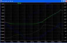
OK, sorry to be specific again, but to exemplify the issue I simulated a vanilla capacitor multiplier filter x 2. Green line is psrr of regulator without, blue line with the multiplier filter. The actual numbers are not of importance, but some of the relative difference will show in practice.
OK, sorry to be specific again, but to exemplify the issue I simulated a vanilla capacitor multiplier filter x 2. Green line is psrr of regulator without, blue line with the multiplier filter. The actual numbers are not of importance, but some of the relative difference will show in practice.
Attachments
thats the logical conclusion - remove linebased RF and transients before they hit the regulator. Using a EF based pre-regulator is not unusual too.I have had good results placing a simple RC filter before the 317/337. It helps roll off the RFI before it reaches the first transistor in the regs. Perhaps we could insert another RC after the 317/337 to filter before the 2nd reg.
Regards
. These regulators just do not filter above 10MHz, that's what John was already saying and everyone of us who do a real work, not only armchair design, know very well. I know the scope background noise.
You don't.
These regulators don't "filter" (whatever that is) anything over 2-3MHz (under 1MHz for the 337). The loop gains are reaching unity around those frequencies. Once the loop gain reached 0dB, there is no line regulation, everything goes through, and only the caps may have some effect.
Any difference to over 20MHz is certainly not related to the regulators.
If you ask me, 2 or 20MHz doesn't make much difference, unless you live on a transmitter pole. Anything that is over the base amp unity loop gain frequency can be safely neglected, but I'm not going to debate such; it is obviously part of your sales pitch.
Last edited:
- Status
- Not open for further replies.
- Home
- Member Areas
- The Lounge
- John Curl's Blowtorch preamplifier part II