Solder or not to Solder, thats the question.
(At least it was in the late seventies )
Yes, wirewrap was used a lot then. But the components and connectors were bigger and manual labor cheaper. Still, there are components in use today in various high-rel applications that are not soldered, but provide contact through similar means to wire-wrap, i.e. cold weld. Most mil and com spec connectors with a lot of pins are made this way, they are simply pressed into plated holes in multilayer PCBs, however the holes and the plating have to conform to strict specs, and the pins are really more similar to small knifes. (edges are very similar to hardened square pin edges on wire wrap components - not a coincidence, no doubt).
I have seen many rebuilds and fixes of wire wrap joints in old equipment by soldering over the joint - a knee-jerk reaction of 'servicemen' with no knowledge of wirewrap. This is likely to form a joint of lesser electrical quality, although at first it may look more mechanically reliable. It's not - the wrap normally uses rather brittle wire but the last few 'windings' offer a form of 'spring' preventing the force that would bend the wire from concentrating into a short lenght thereby breaking the wire. Not so when it's soldered over. The wire wrap joint produces a very good contact even when it's badly corroded from the outside, I've often had to unwind and resolder the wire because it would be seriously weakened from the corosion, and found nice shiny traces fot he cold weld on the pin and wire once I have done so. Ironically, I've had many cases where mechanical forces would actually crack the solder joint holding the wire wrap pin to the PCB

When it comes to choosing solders, in addition to considering ease of soldering and reliability, one of my methodologies is use subjective (listening) bypass testing with RCA cables.
If you have 3 solder types that you wish to test, prepare 4 pairs of RCA cables of identical length and construction.
I suggest using really simple twisted-pair solid-core RCA cables, with the cheap types of RCA connectors that are available in multiple colors.
Have someone else do the preparation and assembly work, and ask them assign one color of RCA jack to one solder. They should keep notes as to what solder went into which colored cable, but they should not show you their notes. IME, it is OK if you know that one cable is different from another, but make sure that you don't know the contents of each cable - otherwise expectation bias will affect the results.
All of the cable pairs except one should be cut at approximately one-half the total length, and soldered back together using one of the solders. Make sure that every detail of each solder joint is as identical as your assembler can manage (other than the temperature differences required between leaded and non-leaded solders). If the cable lengths of the positive and ground leads are offset slightly, you will not need to use heatshrink tubing. But if the solder joints look visibly different (lead-free vs. leaded), you may still want to cover the joints with tubing or tape.
The uncut cable pair will be the reference, to which every soldered cable will be compared against.
Listen for as long as you like, and write notes of how each cable, focusing particularly on how it compares to the reference (rather than like or dislike).
Not all listeners are sensitive to the same sonic artifacts, so if other experienced listeners are available, give them the set of cables and have them conduct the listening tests, too. You may not want to tell them what is different in the cables, as some listeners mentally become incapable of hearing differences if you tell them that they are listening to things that they consider inconsequential, such as solder or resistors.
After all of the listening tests have been completed, determine if any differences were heard or not. If not, then use any solder that is convenient, reliable and easy to work with. If consistent differences were heard, go back to your assembler and find out which solder it was that sounded closest to the no-solder reference.
FWIW, by now I have probably tested a few dozen solders, and to my ears at least, not one has sounded like the direct connection. Among the solders that I tested, there were two solders that I felt sounded reasonably close to the reference (but not to each other). One was a lead-bearing industrial solder made by a large company, and the other was an unleaded solder sold by a small audio accessory company.
Simon7000, I would interested in your results and measurements. But you do state hundreds of joints! would the results have any relevance in a real world situation where maybe 10 solder joints would be the max a signal would pass through, before some component is in the signal path.
I have never known a good solder joint to adde any distortion to any signal of any sort, and would imagine that even with Simons data, single joints would have a figure so low that it is insignificant.
As I mentioned earlier the IPC has a hell of a lot of info on soldering and how to do it correctly, most electronics production companies will train there operatives to IPC-A-610. Nassa and trhe nation physics lab have lots of info on tin whiskers, CAF and other gremlins to keep you awake at night when you have to do high reliability products (commercial, current thinking is a MTBF figure of 10 years before tin whiskers etc may render your gear usless!).
To put soldering into perspective (and how critical it is to the elctronics industry) there are somthing like 6 billion passive components placed a day, thats 12 billion (minimum )solder joints per day, so there has been and still is a lot of studying going on, the main push being to find a solder that is as good as tin/lead eutectic (or tin/lewad/silver).
In the Tektronix service manual for CRT oscilloscope, it is mentioned that solder with 3% silver is to be used for service. There has to be some reason for it.
Gajanan Phadte
Edit: This manual was from pre-ROHS era.
whatever their reason, its not to make it go faster.
Ironic Facts: The best way to stop tin whiskers is to add a minimum of 3% lead to the tin!
And for info NASAs tin whisker page:
NASA Goddard Tin Whisker Homepage
To put the problem into some perspective for all the small electronic devices we have, including computers TV's etc, 0.5 and 0.4mm pitch BGA devices are becoming more common, so distances between conductive surfaces is decreasing, so the whiskers have less distance to grow. And with the ever decreasing operating voltages the chance of a whisker being fused decreases. But as they expect us to change our phones etc every year or so it is not seen as a big issue. Though again for expensive items such as decent camera lenses, figures of 10 years are being quoted.
These are a BGAache to lay out on boards.
http://www.ti.com/lit/an/spraav1b/spraav1b.pdf
Last edited:
The solder I had been using for quite some years has nearly run out. It was a 60/38/2 sn/pb/cu blend.
I hadn't been able to find any to replace it but just did a search of element14's website today and found I can buy 250g 500g and 1KG rolls of it, as well as 60/38/2 sn/pb/ag solder in various sizes.
The copper blend is cheaper. any oppinions on pros and cons of using the copper rather than silver? The copper has a 183c melting point and the silver 179c melting point.
Tony.
The copper blend is cheaper. any oppinions on pros and cons of using the copper rather than silver? The copper has a 183c melting point and the silver 179c melting point.
Tony.
might try a modest 'test'
solder...and resolder
and see what happens
my guess is, the one with high copper content looks like crap, and the one with silver doesn't
I use Cardas Quad tin/lead/copper/silver for just about everything, or Kester for the finer stuff. its VERY unusual for me to need the finer stuff even on fine pitch work, I use cardas organic flux as well because I like paste vs liquid.
I have 2lb of the cardas solder, i'll probably get lead poisoning before I run out
I have 2lb of the cardas solder, i'll probably get lead poisoning before I run out
Not all listeners are sensitive to the same sonic artifacts, so if other experienced listeners are available, give them the set of cables and have them conduct the listening tests, too. You may not want to tell them what is different in the cables, as some listeners mentally become incapable of hearing differences if you tell them that they are listening to things that they consider inconsequential, such as solder or resistors.
the most accurate post in this thread, at least you have listened in blind tests, its not blind speculation about things you think you understand but don't,
nothing makes me laugh more than having a dataman/meter watcher scratch his head in disbelief when you can identify blind 10 or 20 times in a row what they can't hear or measure.
the most accurate post in this thread.....
tell you a story
once I wanted to give a young famely memeber a bit better headphones for his 'walkman'
old days kind of ipod, to those who don't know
anyway, headsets were nothing famcy or expencive
had the choice between two
I chose to plug them into a old style classic parametric equalizer
chose setting, and shifted between EQ and 'straight'
on one headphone I could hear difference, on the other I couldn't
so I decided that the one where I heard a small difference would be the one
and where am I going with this
well, the funny thing is, today I can still hear the strangest small differences or changes.... no matter what kind of solder I choose to use

the most accurate post in this thread, at least you have listened in blind tests, its not blind speculation about things you think you understand but don't,
nothing makes me laugh more than having a dataman/meter watcher scratch his head in disbelief when you can identify blind 10 or 20 times in a row what they can't hear or measure.
Unfortunately, he didn't say that.
Re the EU's ROHS legislation, does anyone know whether the following article is accurate?
Christopher Booker's notebook - Telegraph
There may be hot competition for the title of the craziest EU directive of them all, but a front runner must be one which comes into force at the end of this month. Designed to protect the environment and human health, this law is imposing costs of tens of billions of pounds on businesses, not only in Europe but across the world.
It is based, it now turns out, on scientific studies so flawed that it will only cause further damage to both the environment and health. It will also result in products which the EU itself admits will be less reliable than those we have now.
Some years back an American academic, Timothy Townsend, professor of environmental engineering science at the University of Florida, did studies appearing to show that there was a hazard to health from lead and other metals leaching out of landfill sites into water supplies. This seemed important because of the hundreds of millions of lead-containing electronic products, from cathode ray tubes to the lead solder in computers, that go to landfill.
The EU's legislators went into overdrive to combat this threat with two directives, one of which, on the Restriction on Hazardous Substances in Electrical and Electronic Equipment, comes into force on July 1, banning any use of lead and five other metals in electronic products. This means that all electronics firms in the EU, and anyone wishing to export into the EU, have had to find lead-free substitutes, not least for the mass of solder in every computer circuit board.
Only when the legislation was under way were further American studies carried out, including two involving Prof Townsend himself, which measured the impact of leachate in field conditions and found that the earlier tests had exaggerated the danger by more than 100 times. Under modern landfill quality control, the leachates posed no discernible hazard.
Christopher Booker's notebook - Telegraph
The solder I had been using for quite some years has nearly run out. It was a 60/38/2 sn/pb/cu blend.
I hadn't been able to find any to replace it but just did a search of element14's website today and found I can buy 250g 500g and 1KG rolls of it, as well as 60/38/2 sn/pb/ag solder in various sizes.
The copper blend is cheaper. any oppinions on pros and cons of using the copper rather than silver? The copper has a 183c melting point and the silver 179c melting point.
Tony.
I heard bad reports about soldering simplicity with the one with copper, but if you have used for years and the new roll is exactly the same brand and model, why not? Was it Ersin multicore brand perhaps?
The other one, just make sure is Eutectic (it seems so since you posted a single temp melting point).
Besides this, it shouldn't have any inpact on sound, the conductivity of silver is just a bit more.
Copper was added as a tip saver (SAVBIT) other than that I dont think there is any other benefit.
http://www.farnell.com/datasheets/315929.pdf
http://www.farnell.com/datasheets/315929.pdf
Just my 2 cents..I've tried using silver solder, only to obtain ugly solder joints and no difference that three people was aware of in sound quality...so I will stick with SN/PB at least until I can found it.
Use silver solder that is NOT lead free, maybe read all thread again
In short, what gives bad looking joints is NOT the silver, but the lack of lead.
marce:
"Ersin Multicore Savbit Solder is produced
especially to overcome the problem of ordinary
tin/lead solders dissolving copper."
Basically it is the same reason why Tek used silver-containing solder in its scopes, where there are copper pins (or cables
) it is better to use solder that contains the same metal. This has been explained in more rigorous terms (than I ever could) a couple pages earlier.
Most PCB have tinned pads, therefore any solder containing tin (=all of them) will bond. I think zero issues are also caused by gold-plated pads (they have the advantage of not oxidizing over time, which is the main cause of bad solder joints).
wow i feel less of a noob reading this tread
Last edited:
The encouragement in some earlier posts to resolder joints ought to have been accompanied with a newbie warning: in many cases 'resoldering' is as likely to degrade a good joint as improve a bad one, especially when done by someone who is relatively new to soldering or has lots of experience in doing it badly.
Fairly frequently people pop up in forums like this and say something like "I have redone all the joints in my XXX and now it doesn't work". Usually, they have no circuit diagram (or the knowledge to read it if they had) and little or no test equipment. Remote debugging of an item which has probably several newly introduced bad joints is not easy. Sometimes the unit has to be thrown away - hardly an 'improvement' in its sound!
My take on resoldering is to use it as a repair technique, not an 'upgrade' technique. Only do it to joints which look bad, or symptom diagnosis indicates may be bad, or which misbehave when mechanically disturbed. I sometimes cheat and simply reheat the joint and add a little solder, but at least I know that this is cheating (I should remove the old solder and remake the joint from scratch).
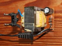
just now slaughtered this wall plug thing, because I wanted the trafo
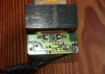
looking at it I thought, maybe I should save/use the diode board
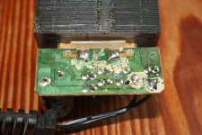
until I looked at solder side
looks real nasty
solder looks shiny and new
any idea why it looks like this
looking at it I thought, maybe I should save/use the diode board
until I looked at solder side
looks real nasty
solder looks shiny and new
any idea why it looks like this
Attachments
- Status
- This old topic is closed. If you want to reopen this topic, contact a moderator using the "Report Post" button.
- Home
- Member Areas
- The Lounge
- Lead vs. Silver solder