Just repeated with a 1 kHz input at 1 V p-p and got an output voltage of 540 mV p-p. Both channels the same. Also checked my bias current. It is right at 1.5 A like the specs say. I cannot figure out what my error is. I looked over the boards again tonight. Something is clearly wrong.
Just repeated with a 1 kHz input at 1 V p-p and got an output voltage of 540 mV p-p. Both channels the same. Also checked my bias current. It is right at 1.5 A like the specs say. I cannot figure out what my error is. I looked over the boards again tonight. Something is clearly wrong.
Swap the probe leads round on the dummy load, does that make any difference?
Just repeated with a 1 kHz input at 1 V p-p and got an output voltage of 540 mV p-p. Both channels the same. Also checked my bias current. It is right at 1.5 A like the specs say. I cannot figure out what my error is. I looked over the boards again tonight. Something is clearly wrong.
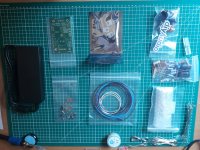
Time to post close up pictures of your build!
Best,
Anand.
Swap the probe leads round on the dummy load, does that make any difference?
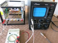
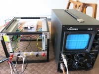
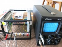
This is to illustrate my thinking (and I fell into the same trap...)
1 - Setting the signal generator to 1k Hz and 1v P-P.
2 - If you place the probes as you expect 'ground' to Black output terminal and probe to Red you get 'reduced' output. About 50%.
3 - If you swap the probes round, ground clip to Red output and the probe to Black you get about 3 volts P-P (+10dB). Which is correct.
All because the Red output terminal is actually amplifier ground...
Attachments
This is to illustrate my thinking (and I fell into the same trap...)
1 - Setting the signal generator to 1k Hz and 1v P-P.
2 - If you place the probes as you expect 'ground' to Black output terminal and probe to Red you get 'reduced' output. About 50%.
3 - If you swap the probes round, ground clip to Red output and the probe to Black you get about 3 volts P-P (+10dB). Which is correct.
All because the Red output terminal is actually amplifier ground...
If this is the case, your scope ground is connected to mains earth, and the ACA ground also to mains earth. Not good for your scope, you get a quite large current through the probe earth connection towards mains earth. Don’t want to count the scopes died this way. Solution is to make scope probe floating from earth.
If this is the case, your scope ground is connected to mains earth, and the ACA ground also to mains earth. Not good for your scope, you get a quite large current through the probe earth connection towards mains earth. Don’t want to count the scopes died this way. Solution is to make scope probe floating from earth.
Thanks, that is a very good warning.
However not the case here. Neither the scope or ACA is at mains ground, they are both 'floating'. The common connection is via the signal generator...
This is to illustrate my thinking (and I fell into the same trap...)
...
All because the Red output terminal is actually amplifier ground...
Makes sense to me! Have to test the amp as it has been designed. Since it’s a common source design, phase is inverted on the output (relative to the input), so the polarity of output terminals are reversed to account for it.
Thanks for SHOWING us the example with photos...
Best,
Anand.
I've taken the amp apart and I am once again going over each and every resistor. I know for a fact that all the transistors and capacitors are installed correctly and have good solder joints. The other obvious connections such as the input, LED, output and power are all connected correctly. For anyone interested in the characteristics of the amp before I disassembled it, here is an FRA plot of gain and phase shift.
Attachments
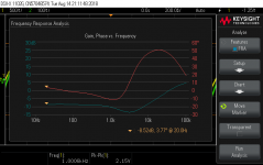
OK, I could shift the input or output polarity and make that happen but why the low gain and the poor frequency response curve? That is what I wonder. Last night I took it all out of the chassis and went over the color code on each and every resistor 2x. I also looked at the solder joints under a magnifier. Caps and transistors are in the proper direction. Bias current is 1.45 A / channel at 12 VDC (I am using the higher voltage Meanwell SMPS). My load is a 100W capable 8 ohm "non-inductive" power resistor. It does measure as being a ~20 microH inductor but it is a pretty pure load.
It seems to me that I've assembled and biased this correctly. The only conclusion I can draw is that while some may like the sound of a Class A due to the harmonics, the ACA V1.6 is a pretty low gain amp with some phase shift and frequency response limitations at very high frequencies. Most likely will those limitations will not change the sound for most people and maybe I should put the instruments away.
It seems to me that I've assembled and biased this correctly. The only conclusion I can draw is that while some may like the sound of a Class A due to the harmonics, the ACA V1.6 is a pretty low gain amp with some phase shift and frequency response limitations at very high frequencies. Most likely will those limitations will not change the sound for most people and maybe I should put the instruments away.
Rossinsd,
Did you read post #106?: http://www.diyaudio.com/forums/the-diyaudio-store/256660-amp-camp-amp-kit-v1-6-a-11.html#post5518089
Is it low gain? Yes, +10dB. But not negative gain. That you will have to explain. Are the 100 ohm, 1K, 10K resistors measured with a DVM and in the right places? I almost goofed on my build actually.
Best,
Anand.
Last edited:
Thanks for the reply. Yes, I read the post but I fail to appreciate how a non-polar device (the power resistor) polarity should matter. I also understand that the red output binding post is actually at ground potential because of the amp design. I have checked the component placement so many times now that I am 100% convinced that no br-bl-bl-bl has been put where a br-bl-bl-br should be.
The amp does play. If I use my phone as a source and connect to some NHT speakers it is somewhat louder than the phone can play. It can obviously provide more current into a speaker than the crappy amp in the headphone circuit of the phone. I started this whole FRA testing stuff because it seemed like this was a pretty weak 6-8 watts with the NHT speakers.
Negative gain is how the data is presented in the FRA plot I showed in the message attachment. That is the voltage output is lower than the input. However the output impedance is much lower and so the output current can be higher. The - 10 dB is based on voltage, not on power.
Thanks for the response and suggestions.
Rossinsd,
Personally I think your amp probably works fine. I do believe that it has to do with your measurement setup as was shown on post 106. I don’t think it has anything to with the 8 ohm power resistor you are using, although I generally don’t place a load on most of my solid state builds to just test gain. The polarity reversal has to do with the configuration of the gain stage which is a common source design which intrinsically reverses polarity, period. Math is math and 1V P-P input should be 3V P-P output on this amplifier.
That being said, if you are satisfied that the amp is working, enjoy the music")
Kind regards,
Anand.
Personally I think your amp probably works fine. I do believe that it has to do with your measurement setup as was shown on post 106. I don’t think it has anything to with the 8 ohm power resistor you are using, although I generally don’t place a load on most of my solid state builds to just test gain. The polarity reversal has to do with the configuration of the gain stage which is a common source design which intrinsically reverses polarity, period. Math is math and 1V P-P input should be 3V P-P output on this amplifier.
That being said, if you are satisfied that the amp is working, enjoy the music
Kind regards,
Anand.
As stated above, you are sure that you don’t short circuit the output as explaned in #106?
If you connect channel A probe ground clip to ground of signal generator, and connect the generator to input and ground of aca, and channel B ground probe clip to the hot output (black connector), then your ls output is shorted to ground. Use only the groundclip of channel A to be sure.
If you connect channel A probe ground clip to ground of signal generator, and connect the generator to input and ground of aca, and channel B ground probe clip to the hot output (black connector), then your ls output is shorted to ground. Use only the groundclip of channel A to be sure.
- Home
- The diyAudio Store
- Amp Camp Amp Kit 1.6/1.8