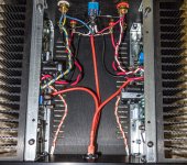
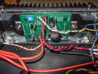
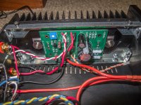
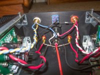
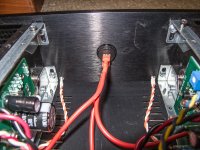
My problems were due to my own confusion. I have posted the latest FRA from one of the channels, the other is the same. It is exactly what is promised. The change came from putting the ground of the scope on the right output binding post (as was kindly mentioned a couple of days ago). But I am still posting photos of my assembly for others to see if it helps them. I did the front switch wiring a little different and with spade connectors to make it easy to take things apart. I also used different wire since I like the silicon insulated with with finer conductors. Critiques are appreciated.
Thanks to everyone who has commented and helped me learn. I really appreciate it.
Thanks to everyone who has commented and helped me learn. I really appreciate it.
Attachments
-
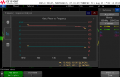 left-plot.png23 KB · Views: 576
 -
 Rossinsd_ACA_ (1 of 7).jpg915 KB · Views: 568
 -
 Rossinsd_ACA_ (2 of 7).jpg955.7 KB · Views: 564
 -
 Rossinsd_ACA_ (3 of 7).jpg892.6 KB · Views: 549
 -
 Rossinsd_ACA_ (4 of 7).jpg819.2 KB · Views: 535
 -
 Rossinsd_ACA_ (5 of 7).jpg906.3 KB · Views: 235
 -
 Rossinsd_ACA_ (6 of 7).jpg959.5 KB · Views: 209
 -
 Rossinsd_ACA_ (7 of 7).jpg332.8 KB · Views: 229
")
Has the August 14th batch of the ACA 1.6 been shipped on schedule?
I haven't received a shipping notification yet...
Most of batch 1 (July 31st) shipped on Aug 2nd, with the remainder around the Aug 8th. Please email contact@diyaudiostore.com with your order number if you have any concerns. Batch 2 (Sep 15th) has not yet shipped.
Hi all,
OK, this is an amazing amp, massive amount of details,massive.
even with not the best source it amazed me,
my setup :
Chromecast audio --(optic cable)>fiio d03k(-->ACA-->Monitor Audio BX2(92db)
i was wondering,
does the LED's are part of the circuit or can i dim them a bit with small resistors with no effect on the amp?
thanks for everyone involved, great work, lots of fun!
Hello, greetings to all.
Sorry if you do not understand what I say, I do not speak English and I use the Google translator.
I got the ACA 1.6 kit, 11 days after Jason notified me that the kit had been shipped. All correct and in perfect condition. The chassis arrived at the end of June.
Well, it is already mounted, running without problems, for now I use a 19v portable PC PSU waiting for me to get the 24v PSU.
I am going to use it as a simple two-channel amplifier and I intend to include a preamplifier that I built in the 80s with a cable remote control.
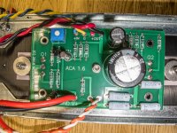
That's why I installed terminals on the PCB to be able to connect quickly and conveniently.
The PCB has 5 holes to fix to the radiator, the radiator is machined for it, although in the kit only comes a separator to fix the PCB because the terminals of the mosFet make of the PCB. But when installing screw terminals for the Vcc power supply and the speakers, I fixed the PCB by means of 5 spacers to avoid tensions in the terminals of the mosFet when tightening the screws. It must be borne in mind that when fixing the PCB to the radiator, either with the central screw, or with the 5, we are connecting to the chassis the ground line of the PCB, since two of the holes are in the ground tracks.
The connector of the PSU is uninsulated metal, so the negative of the Vcc is connected through the chassis to the PCB of the 1.6 amps, the chassis is the conductor of the return signals to ground.
It is only necessary to connect the ground lines of the isolated terminals, which are the signal inputs and the speakers. Keep in mind that the colors of the speaker terminals have been inverted to respect the input phase (in reality the red speaker terminals are the connection of these to ground and have been attached to the negative connector of the PSU for its proximity to form a comfortable common ground point).
Those who have wired the complete ground lines should know that the signals are going through two different paths, the wiring and the chassis. In a final stage this surely does not affect the sound at all, but in the low signal pre-stages they give buzz problems. PCBs can be isolated by inserting a thin sheet of plastic, with a hole for the screw, or a nylon washer and changing the metal screw with a nylon screw. Thus the chassis is only as an electrical shield.
We have three ways to wire to experiment.
In short, a small amplifier easy to build that works very well. When turning it on, it starts up smoothly, taking a few seconds to reach the maximum current consumption that stabilizes by lowering a bit as it warms up, which is why the speakers do not emit any ignition noise. Yes they emit a small "plop" when turning it off. Sticking the ear to the tweezer and the woofer I am not able to listen neither hissss nor hummmm, so the noise that reproduces will depend on the preamp and the sources that we connect to it. I'm not going to value the quality of the sound because that is very subjective and depends on the hearing and personal tastes of each listener, but to me it seems a clean and pleasant sound with very good bass response. Age degrades our hearing, so when you install the preamp, you may raise the treble a little.
I do not have instruments to make serious measurements of the ACA, but with my rudimentary means I have been able to make some measurements.
Voltage of the power supply 19,4v dc
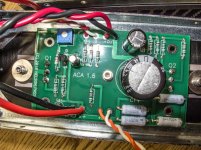
I adjust P1 to have half the supply voltage in drain of Q1, 9.7v
At the midpoint of R1 // R2 - R3 // R4 (+ of C1) we have 10.18v
The current consumption is 0A just when turning on, it goes up in about three seconds to 1.36A, for another two or three seconds it drops to 1A, and in another two seconds it reaches the maximum of 1.45A. From that point and as the radiators and the front are heated (minimum 20 minutes), the current goes down until it stabilizes at 1.36A when the thermal equilibrium is established (the heat that the radiators absorb from the transistors is equal to that dissipate the environment and stabilizes its temperature)
After 2 hours of heating the temperature in the central zone of the radiator is 50.4 ° C, the room temperature is 29.9 ° C (What heat!), That is to say that the temperature of the radiators stabilizes 20.5 ° C above of the room temperature.
I have a simple generator of BF DIY (range of 10Hz to 200KHz) with which I could measure: except for a small oscillation around 100Hz, flat frequency response until 120KHz, where it starts to fall, being the fall to 200KHz of about 2db. Voltage gain by injecting 100mV rms at 440Hz with no load on the speaker output: 365mV on one channel and 368mV on the other. About 11.2db
I think 4 or 5 W are enough to sound at a moderate level and even high a medium room of any home using speakers with SPL of 87 to 90 db, so, if at some peak I appreciate distortion or clipping, I will consider the version bridged.
At the moment I am enjoying a lot of how the music reproduces the ACA, and in winter it will serve to warm my hands.
Thank you, Mr. Pass!
Thanks, DiyAudio!
Greetings, partners.
Sorry if you do not understand what I say, I do not speak English and I use the Google translator.
I got the ACA 1.6 kit, 11 days after Jason notified me that the kit had been shipped. All correct and in perfect condition. The chassis arrived at the end of June.
Well, it is already mounted, running without problems, for now I use a 19v portable PC PSU waiting for me to get the 24v PSU.
I am going to use it as a simple two-channel amplifier and I intend to include a preamplifier that I built in the 80s with a cable remote control.
That's why I installed terminals on the PCB to be able to connect quickly and conveniently.
The PCB has 5 holes to fix to the radiator, the radiator is machined for it, although in the kit only comes a separator to fix the PCB because the terminals of the mosFet make of the PCB. But when installing screw terminals for the Vcc power supply and the speakers, I fixed the PCB by means of 5 spacers to avoid tensions in the terminals of the mosFet when tightening the screws. It must be borne in mind that when fixing the PCB to the radiator, either with the central screw, or with the 5, we are connecting to the chassis the ground line of the PCB, since two of the holes are in the ground tracks.
The connector of the PSU is uninsulated metal, so the negative of the Vcc is connected through the chassis to the PCB of the 1.6 amps, the chassis is the conductor of the return signals to ground.
It is only necessary to connect the ground lines of the isolated terminals, which are the signal inputs and the speakers. Keep in mind that the colors of the speaker terminals have been inverted to respect the input phase (in reality the red speaker terminals are the connection of these to ground and have been attached to the negative connector of the PSU for its proximity to form a comfortable common ground point).
Those who have wired the complete ground lines should know that the signals are going through two different paths, the wiring and the chassis. In a final stage this surely does not affect the sound at all, but in the low signal pre-stages they give buzz problems. PCBs can be isolated by inserting a thin sheet of plastic, with a hole for the screw, or a nylon washer and changing the metal screw with a nylon screw. Thus the chassis is only as an electrical shield.
We have three ways to wire to experiment.
In short, a small amplifier easy to build that works very well. When turning it on, it starts up smoothly, taking a few seconds to reach the maximum current consumption that stabilizes by lowering a bit as it warms up, which is why the speakers do not emit any ignition noise. Yes they emit a small "plop" when turning it off. Sticking the ear to the tweezer and the woofer I am not able to listen neither hissss nor hummmm, so the noise that reproduces will depend on the preamp and the sources that we connect to it. I'm not going to value the quality of the sound because that is very subjective and depends on the hearing and personal tastes of each listener, but to me it seems a clean and pleasant sound with very good bass response. Age degrades our hearing, so when you install the preamp, you may raise the treble a little.
I do not have instruments to make serious measurements of the ACA, but with my rudimentary means I have been able to make some measurements.
Voltage of the power supply 19,4v dc
I adjust P1 to have half the supply voltage in drain of Q1, 9.7v
At the midpoint of R1 // R2 - R3 // R4 (+ of C1) we have 10.18v
The current consumption is 0A just when turning on, it goes up in about three seconds to 1.36A, for another two or three seconds it drops to 1A, and in another two seconds it reaches the maximum of 1.45A. From that point and as the radiators and the front are heated (minimum 20 minutes), the current goes down until it stabilizes at 1.36A when the thermal equilibrium is established (the heat that the radiators absorb from the transistors is equal to that dissipate the environment and stabilizes its temperature)
After 2 hours of heating the temperature in the central zone of the radiator is 50.4 ° C, the room temperature is 29.9 ° C (What heat!), That is to say that the temperature of the radiators stabilizes 20.5 ° C above of the room temperature.
I have a simple generator of BF DIY (range of 10Hz to 200KHz) with which I could measure: except for a small oscillation around 100Hz, flat frequency response until 120KHz, where it starts to fall, being the fall to 200KHz of about 2db. Voltage gain by injecting 100mV rms at 440Hz with no load on the speaker output: 365mV on one channel and 368mV on the other. About 11.2db
I think 4 or 5 W are enough to sound at a moderate level and even high a medium room of any home using speakers with SPL of 87 to 90 db, so, if at some peak I appreciate distortion or clipping, I will consider the version bridged.
At the moment I am enjoying a lot of how the music reproduces the ACA, and in winter it will serve to warm my hands.
Thank you, Mr. Pass!
Thanks, DiyAudio!
Greetings, partners.
Hello,
thanks for you guys for providing this ACA as a kit.
I ordered 2 kits and 2 cases from batch 2. The cases have already arrived a while ago, in perfect condition. Real nice cases. I assembled one, and inspected the other.
Unfortunately the shipping costs to EU for the power supply turn out to be quite high.
I found a EU supplier that also sells the power supply with reasonable EU shipping costs. I hope it is ok to post this here, of not, you may remove this.
GST120A24-P1M MEAN WELL - Pwr sup.unit: switched-mode | TME - Electronic components
The picture seems wrong for the plug, according to the documentation the model ending in "-P1M" (which I linked) has the correct one.
You still need to order a EU power cord, here is a pre-selection from the same supplier
Transfer Multisort Elektronik - On-line Catalogue | 250 000 products offered.
Greetings Joram
Got mine from Germany Elektronik und Technik bei reichelt elektronik gnstig bestellen
The Meanwell PS is available in 2 versions, the one you link to, and the other with the connector used in the ACA. Reichelt has both versions. Let me know if you cannot find the correct number. I will look it up for you. Groeten.
The Meanwell PS is available in 2 versions, the one you link to, and the other with the connector used in the ACA. Reichelt has both versions. Let me know if you cannot find the correct number. I will look it up for you. Groeten.
Some photos:
Greetings.[/QUOT
I'm sorry, I have not been able to upload them.
- Home
- The diyAudio Store
- Amp Camp Amp Kit 1.6/1.8