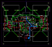
I might make a few changes, nothing critical, except one I recommend. Place the pass transistor symmetrical between the caps. That gives the best distance to either cap for heat and leaves the max space for a heatsink.
Jan
Which caps Jan, can you please name them?
C101, C201.Which caps Jan, can you please name them?
You are mistaken. What is shown is a two stage shunt regulator. The first stage consists of a current source and zener diode, having a line rejection @ DC of about 80 dB. The second stage consists of a resistor and LM329 precision reference IC, which adds another 60dB of line rejection @ DC. I very much doubt that you can exhibit a >20 year old schematic containing a cascade of two shunt regulation zener_diodes/ICs, in which the first shunt regulator is biased by a current source and the second is biased by a resistor.
_
Then again Mark, if you feed the ref from the regulated output, you get all that for free. What is the reason you chose not to do it that way? (Same for supplying the eror amp).
Jan
I recall seeing similar many times over a few decades.You are mistaken. What is shown is a two stage shunt regulator. The first stage consists of a current source and zener diode, having a line rejection @ DC of about 80 dB. The second stage consists of a resistor and LM329 precision reference IC, which adds another 60dB of line rejection @ DC. I very much doubt that you can exhibit a >20 year old schematic containing a cascade of two shunt regulation zener_diodes/ICs, in which the first shunt regulator is biased by a current source and the second is biased by a resistor.
_
It's just a pre-regulator and regulator.
Why didn't you choose to feed the ref from the regulated output?
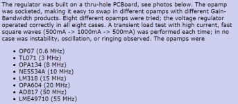
I wanted to work with a lot of different opamp types (see Figure1 below), possibly even the very expensive LT1028.
LT1028 has issues in the SuperRegulator...oftimes fails to start.
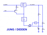
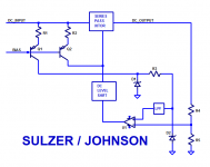
The additional cost was modest: 3 extra components (see Figures 2 and 3 below). Whereas the Jung/Didden has one component ("R3") biasing the reference diode ("D2"), my circuit has four components (R1, Q1, D1, R3). These are not high priced devices.
I also am not completely comfortable with Figure 2. Notice that it includes a positive feedback loop from Output to OpampIn+ to Output, in addition to the normal negative feedback loop. I would prefer there to be a lot more attenuation in the positive feedback path; in Figure 2 the attenuation is (Zd2 / (R3 + Zd2)) which is "only" ~ -70dB to -80dB. But the gain of the opamp at DC can be as high as +146dB if you select the AD797 opamp or +150dB if you select the LT1028. It makes me uncomfortable. The price to eliminate my discomfort is low: just 3 extra parts. Easy decision.
Same issue with the opamp PWR_IN terminal: the positive feedback loop from Output to Supply+ back to Output, simply makes me uncomfortable. So I removed it, at low cost.
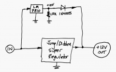
(By the way, there is an equally inexpensive solution for the "might not start up" problem, which everybody and their dog will agree is 100% effective: Install a 3 terminal IC voltage regulator that produces (Vout - 2V) and connect it to the SuperRegulator output with a diode. Presto, the LM7810 pulls up the regulator output to +9V, which is plenty enough to wake up the Super Regulator and let it function normally. The Super Regulator then takes over and regulates the output to +12V. Thanks to the diode, the LM7810 ceases to have any further effect upon the output. Total cost? 3 components.)
_
Attachments
Last edited:
I recall seeing similar many times over a few decades.
It's just a pre-regulator and regulator.
I very much doubt that you can exhibit a >20 year old schematic containing a cascade of two shunt regulation zener_diodes/ICs, in which the first shunt regulator is biased by a current source and the second is biased by a resistor.
i used a similar solution for a work product last year.
it was quite amusing in the design review to listen to all the "pots-shots" and accusations that it wouldn't/couldn't work; apparently it was too simple.
nothing quiets naysayers like a working prototype ...
")
mlloyd1
it was quite amusing in the design review to listen to all the "pots-shots" and accusations that it wouldn't/couldn't work; apparently it was too simple.
nothing quiets naysayers like a working prototype ...
mlloyd1
...
(By the way, there is an equally inexpensive solution for the "might not start up" problem, which everybody and their dog will agree is 100% effective: Install a 3 terminal IC voltage regulator that produces (Vout - 2V) and connect it to the SuperRegulator output with a diode. Presto, the LM7810 pulls up the regulator output to +9V, which is plenty enough to wake up the Super Regulator and let it function normally. The Super Regulator then takes over and regulates the output to +12V. Thanks to the diode, the LM7810 ceases to have any further effect upon the output. Total cost? 3 components.)
_
You're rightI very much doubt that you can exhibit a >20 year old schematic
containing a cascade of two shunt regulation zener_diodes/ICs, in which the first shunt regulator is biased by a current source and the second is biased by a resistor.
For those who seek a foolproof circuit that guarantees every possible Super Regulator with every possible choice of opamp, will start up correctly, 100.00% of the time, ...
... but who are horrified and nauseated by post #1146 which uses (gasp!!) a voltage regulator IC to start up a discrete voltage regulator, ...
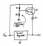
then I offer the modification below. Parts count has exploded: there are now four components. A new resistor has been added. The blasphemous voltage regulator IC has been excised, and replaced with a theologically approved Darlington transitor. A discrete transistor. Ahhh, that's better.
Q1 and D1 should be rated for a continuous output current equal to, or greater than, the maximum load the Super Regulator might drive. Even though they are only active in the first few hundred milliseconds of startup behavior, it's better to be safe than sorry. I wouldn't go so far as to mount Q1 on a heatsink, however. There's overkill and there's ridiculous, indefensible overkill.
_
... but who are horrified and nauseated by post #1146 which uses (gasp!!) a voltage regulator IC to start up a discrete voltage regulator, ...
then I offer the modification below. Parts count has exploded: there are now four components. A new resistor has been added. The blasphemous voltage regulator IC has been excised, and replaced with a theologically approved Darlington transitor. A discrete transistor. Ahhh, that's better.
Q1 and D1 should be rated for a continuous output current equal to, or greater than, the maximum load the Super Regulator might drive. Even though they are only active in the first few hundred milliseconds of startup behavior, it's better to be safe than sorry. I wouldn't go so far as to mount Q1 on a heatsink, however. There's overkill and there's ridiculous, indefensible overkill.
_
Attachments
I wish to use Super Regulators in Paradise phono stage I am built at the moment instead of proposed shunt regulators. It got better results in LA listening test article. I have the following op-amps: AD825,OPA134,OP604. NE5534, LME49710. Which one to use in this MC phono stage?
I wish to use Super Regulators in Paradise phono stage I am built at the moment instead of proposed shunt regulators. It got better results in LA listening test article. I have the following op-amps: AD825,OPA134,OP604. NE5534, LME49710. Which one to use in this MC phono stage?
It doesn't really make a difference for the regulator whether to drive a phono stage or another small-signal circuit.
All the opamps you mention are suitable. My personal favorite is the AD825, never had any issues with start-up, always rock-stable. But it's a bit subjective, I admit.
Jan
If you post your calculations, I will double check them for you.How much additional current is taken by the regulator circuit ? In some cases it's important thing.
How much additional current is taken by the regulator circuit ? In some cases it's important thing.
The main contributors are the supply current from the opamp (found in datasheet), current through the voltage reference and through the feedback network.
AD825 typ. 6.5 mA
Reference 1-5 mA depending of design
Feedback 1-10 mA depending of output voltage and design
Which opamp do you plan to use?
Jan
opa445ap
- Home
- The diyAudio Store
- Super Regulator