I was trying to take a afternoon sleep and realised I posted the wrong schematic. I was interperting the online simulator the wrong way when drawing the schematic.
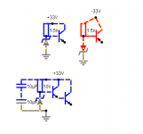
This is how you should wire the circuit up.
The second one with two transistors allows you to dump more power, the transistor emitter connected to base disipates the base current of output times vcc-zener voltage-0.6.
Output dumps ce voltage times load current. which is vcc minus zener minus 1.2v. Output voltage approx zener voltage -1.2 volts
The zeners keeps a constant voltage at base, and output voltage of transistor is dependant by base voltage.
Attachments
Last edited:
Are you ruling out surface mount for the op-amp? AD825 is only in surface mount.
An L-pad can sound better than a pot. The series element is a resistor and the nasty sounding pot is only shunting to earth. I just did a couple of conversions like that, with something like a 2 k or 5k in the signal path, followed by the 50k pot, in those cases, to earth, and wiper to earth.
Should the input and output grounds not be separate to the earth star
I am planning to use LME49710, which seems to have better PSRR and noise specs than AD825, don't know if that matters?but I can also put Smd option if anyone else interested.
I think 1K ohm is to maintain input impedence minimum specs if the pots viper is at zero ohm( max volume). The resistors at the gate are 200 ohm gate stoppers to prevent bf862 from oscillating and recommended. At both upper and lower Jfets gate. Perhaps I should position them closer to gate?
The diode D6 is copied from B1 design . It is parallel to the top voltage divider resistor.on Pcb the position has changed a bit. I don't know it's use.
I am using a stepped ladder type, attenuator I made myself . Working really well and essentially works as an Lpad. It always has a resistor in path, with minimum attenuation at 3dB so that is why I skipped the 1K resistor in original design, but I can add if I am wrong to design.
About perfect star wiring ,I changed it per Jan's recommendations. I don't know the reasons.
Last edited:
Super Regulator – diyAudio Store
I mean when I click link for measurements it tells you to look for vol 4, but you have to buy vol4 to see the actuall performance of the "super regulator".
If I was a customer, I would not consider this product because there are no specification on ripple rejection.
The output dosen't seem to be short protected either.
LM317 has good ripple rejection and is short proof. Is there any reason for me to consider this regulator over it? It also consumes much less components.
As I noted above, some specs are here:
Partly here: Downloads | Linear Audio
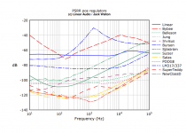
scroll down to 'Color graphs for Jack Walton's regulator article in Vol 4'
One figure is the pos PSRR - and indeed, the 317 is a joke.
So, it is all there but you have to get it.
And you can also purchase the article itself if you don't want the whole Volume for a whopping € 0.99.
Jan
Attachments
Last edited:
")
If I am not mistaken Jung is the super regulator with refrence to graphs? I did some google search on it.
It seems to have superior ripple rejction performance and very low output impediance I like it.
Indeed.
Very perfect for solid state low current applications. All for pennies on the dollar! Love Jan's dedication and work!
Best,
Anand.
If I am not mistaken Jung is the super regulator with refrence to graphs? I did some google search on it.
It seems to have superior ripple rejction performance and very low output impediance I like it.
Yes it's the Jung. I worked on it with Walt Jung in, ohh, 1994 I think ;-)
You'll see it referred to as 'Superreg', 'Jung', 'Didden', 'Jung/Didden', even 'Sulzer' whos design even predates ours, etc.....
There was a steady stream of improvements through the years.
What's in a name.
Jan
As far as I am corcerned it looks good to go, but note that I did not check the B1 circuitry and related issues. Don't want to meddle in that; I know there are several threads here on the B1.
Your setup with the psu in the middle and the two channels on each side is a logical and excellent setup. Compact, no long traces, yet nicely separated channels. The important thing with the grounding is making sure that there is no signal ground current and supply ground current in the same trace, and that is taken care of.
As to that LME49xxx in the regulator, I haven't tried that myself, but so far the only opamp that I know of that sometimes causes issues is the AD797. If you have that LME laying around, by all means give it a try.
Jan
Last edited:
As to that LME49xxx in the regulator, I haven't tried that myself, but so far the only opamp that I know of that sometimes causes issues is the AD797. If you have that LME laying around, by all means give it a try.
Jan
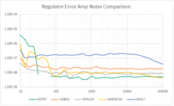
LT1028 has issues in the SR...oftimes fails to start.
LME49710 performance is close to AD797.
FWIW -- in operation, mine all use the AD825. This includes two preamplifiers (Adcom GFP565 and Crown IC150a).
have you tested LME49710 in regulator or is it in General?LME49710 performance is close to AD797.
.
have you tested LME49710 in regulator or is it in General?
Yes, but noise is only one of 4 factors which affect the listening experience.
Attachments
Yes, but noise is only one of 4 factors which affect the listening experience.
Curious , what are the other three?
I reckon he might be talking about the correlation coefficients shown in Table 8 of the Linear Audio article that includes both electrical measurements and listening tests.
(here is a link). Costs €0,99 to download the article.
(here is a link). Costs €0,99 to download the article.
Mark , my Cheapmodo is working well, running around the house snubbing everything I can open ( and some I shouldn’t). Seting up raw supplies for 24 Jung boards for new dac, preamp and phono.
I did download the Linear Audio power supply article and yours - both useful and recommended.
I did download the Linear Audio power supply article and yours - both useful and recommended.
Last edited:
- Home
- The diyAudio Store
- Super Regulator