Yes of course. Walt Jung and Jan Didden were aware of these advantages back in 1994, and are still aware of them today. However, they (and most other people) have concluded that the disadvantages of MOSFET pass transistors in Jung/Didden SuperRegulators, outweigh the advantages. So most people continue to build SuperRegulators using BJT pass transistors.BJT transistors are preferred types for pass tr. in super regulators. But some designers use mosfets . Is there any advantage in using mosfets?
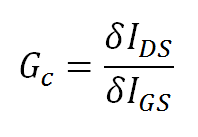
One area in which MOSFETs are clearly superior, is speed. In particular, their transition frequency (where incremental gain Gc falls to unity), is 3X to 10X higher than BJTs of the same current and voltage rating. If you believe that pass transistor speed is an important aspect of SuperRegulator performance (historical reminder: Walt Jung chose the D44H11 BJT because it was fast), perhaps MOSFETs would make you even happier. For a MOSFET, fT is that frequency at which Gc falls to unity

Another portion of the Jung/Didden SuperRegulator where MOSFETs have a clear advantage is: the current source. Unlike a BJT pass device, the MOSFET has a very low gate current (zero), and more importantly, this gate current is known and constant over temperature, output voltage, and output current. You can design the current source without worrying about variations in the base/gate current drawn by the pass device. This in turn allows you to completely omit the emitter follower found in Walt's earliest SuperRegulator designs (opamp -> emitter follower -> current_source + pass transistor control electrode), since you can confidently design the current source to be within the capabilities of the opamp output. No EF needed, saving a few precious degrees of phase lag.
I will stop now, in order to allow kamis + others to write out a list of MOSFET disadvantages, which leads most designers to choose a BJT pass transistor instead.
Attachments
Last edited:
In theory, yes but.... you have also a capacitance you must consider. Requires lot's of current in order to get speed.One area in which MOSFETs are clearly superior, is speed. In particular, their transition frequency (where incremental gain Gc falls to unity), is 3X to 10X higher than BJTs of the same current and voltage rating..
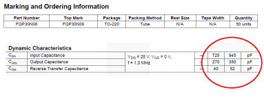
Let's do a comparison of the D44H11 BJT at 50mA, and the Fairchild FQP30N06 MOSFET (datasheet) also at 50mA.Cons: MOSFET has Higher capacitance's ... .
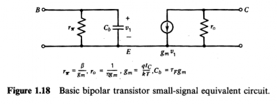
The Hybrid Pi model of a BJT is attached (Gray and Meyer, p.36). To calculate its base-emitter capacitance we need the base forward transit time tauF and the transconductance gm.
tauF is just another way of expressing the transistor speed: (tauF x 2 x pi x fT) = 1. Since we know the fT of the D44H11 is 75 MHz, that lets us calculate tauF = 2.12 nanoseconds.
Transconductance gm is simply (Ic / (kT/q)). At room temperature, (kT/q) = 26 millivolts. At Ic = 50 milliamps, gm = 1.92 siemens.
The base-emitter capacitance of the D44H11 at 50mA is thus (tauF x gm) = 4077 picofarads. Pound it out on your calculator if you don't believe me: More than four thousand picofarads. And it increases linearly with collector current.
The gate-to-source capacitance of the FQP30N06 is 945 pF (see datasheet excerpt below), and the gate-to-drain capacitance is 350 pF. Add them together and you find that the total capacitance at the gate is 1295 picofarads. That's 3.1X lower than the base capacitance of the BJT. Remember that both devices are operated as followers, so there is no Miller-effect multiplication of capacitance in either of these circuits.
Thus we see that in some cases, SuperRegulator pass transistor capacitance is significantly lower for MOSFET than for BJT. Contrary to the conventional wisdom.
Attachments
How higher Vgs (usually 3.5-4v, or 1.5 for Hitachi laterals) influence regulator quality?Cons: Higher capacitance's, higher Vgs, lower transconductance
Pros: Lower "base" current.
One way for BJT enthusiasts to win the capacitance war (and also the speed war) vs MOSFETs, is to realize that Walt Jung's pass transistor D44H11 from his 1995 article is (a) old; (b) rated for 8000 mA, whereas most Jung/Didden SuperRegulators only supply 50-100 mA.
Armed with this knowledge, a quick search for 200mA BJTs with fT significantly better than the D44H11, reveals the mighty Panasonic 2SC555600 (datasheet) and its bretheren. These are little bitty surface mount packaged UHF transistors, only rated for 10 volts and 300 milliwatts. But oh my lord, their fT is 6000 MHz. A factor of 80 higher than the D44H11. So their base capacitance is a factor of 80 less than the D44H11.
Put 5 of these guys in parallel, cascode their collectors to keep VCE = 4.0 volts, and run each one at 25 mA. Presto: 125 mA output current (more than enough for a preamp, phonostage, lineamp, DAC, or active crossover). Dissipation is 100mW each, well within the 300mW/device rating. Emitter ballast resistors help smooth out any VBE mismatch. The whole assembly is 10X faster than a modern power MOSFET, and (80/5) = 16X lower base capacitance than the D44H11. Nice.
However, these Panasonic BJTs are soon to be discontinued, so Buy Now While You Still Can. FYI, DigiKey has 5700 in stock.
Another intriguing choice is the venerable PN2369A, developed in the 1960s for discrete RTL logic in supercomputers. It costs $0.02, has an fT of 700 MHz, and comes in a thru-hole package for those too old, too set in their ways, or too blind to use SMD. Put ten of them in parallel? Give it some thought.
How to boost the output current of the Super reg? Or, what is its limit?
Reduce R1 and choose a Q1 having higher hfe.
What else?
First of all, you need to remember that the opamp will be able to feed a certain amount of current. If you go near its actual limits, you need to consider heatsinking of the IC - it may not require a lot of it, but just don't forget ensuring that everything runs cool. Read the thread again, you will find a relevant post of Jan.
So, since your opamp's output current is limited and known, you can go as big as your pass transistor's hfe allows you to go, given the opamp's current. Then maybe you should look for an opamp able to feed more current.
To increase the maximum output current, modify the design.
One possible design mod would be to substitute a high current depletion mode MOSFET + plenty big heatsink, for the series pass transistor. Perhaps something like the IXTP3N100.
Another possible design modification would be a 2-transistor replacement for the D44H11. You could consider a Complementary Feedback Pair ("Sziklai Pair"), a Darlington pair, or a depletion MOSFET-BJT pair. The Supertex DN4250 depletion MOSFET that Walt Jung advocates, might be an especially good choice.
A third possible design modification would be to use the Jung/Didden SuperRegulator with a conventional PNP (on big heatsink) current booster. The SuperReg supplies the first 75mA and the PNP supplies all the rest. Chose R1 = (VBE / 75mA) in the generalized schematic below.
In each case, your designer would want to verify that the modified circuit was unconditionally stable, and that its regulation characteristics (output impedance, line regulation, load regulation, noise, etc) remained excellent.
An externally hosted image should be here but it was not working when we last tested it.
Audiostrat, I have noted that Jung/Didden mentioned about it in their articles.
Mark, thank you for the details explanation. Maybe, I can do an experiment of dropping in a Darlington transistor in lieu of D44H11 and see what happens. If it does not work, then I have to do study the recommended modifications in depth.
Forget to make it clear, the target current output is about ~3A.
Forget to make it clear, the target current output is about ~3A.
3A for a +/- 13.7 V supply? -- I am wondering where you're going here. Perhaps for a mixing board in a recording studio, in which case you'd be better off having multiple regulators as there will be plenty of reverse PSRR.
First of all, you need to remember that the opamp will be able to feed a certain amount of current.
It is not the opamp that feeds the base current for the pass device - it's the current source that does that.
That said, it is of course the opamp that has to absorb that current if you unload the regulator. So if you want your reg to be working between zero load and max load, the effect will be that the opamp has to be able to absorb the full current source current.
In the end the effect will be the same, but I thought I'd mention the difference for better understanding.
Re: use of MOSFET pass device: for me the biggest disadvantage is the much lower device gain, which means less loop gain which means less corrective feedback which means lower perfomance in the audio band.
Jan
Re: use of MOSFET pass device: for me the biggest disadvantage is the much lower device gain, which means less loop gain which means less corrective feedback which means lower perfomance in the audio band.
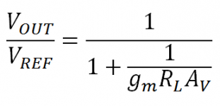
Jan, I suspect you're speaking about the transconductance gm of the series pass transistor. Work out the transfer function of a voltage regulator consisting of a pass transistor with transconductance "gm", driving a load resistor "RL", with an error amplifier whose (finite) open loop voltage gain is "Av". From the voltage reference input to the regulator output, the transfer function is

BJT transconductance is higher than MOSFET transconductance; it's true. But the ratio is less than ten to one.
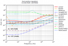
Opamp open loop gain Av varies much more than ten to one; for the AD825 (76dB) versus the AD797 (146dB), the ratio is 3000 to 1. Yet the impact upon measured low-frequency Zout in Jack Walton's curves, is only 10 to 1 (see attachment). Conclusion: as long as (gm x Av) is big enough, you'll get world class performance. Want to use a MOSFET pass transistor? It'll be wonderful; just make sure to pick an opamp whose open loop gain Av is greater than 80 dB.
Attachments
It is not the opamp that feeds the base current for the pass device - it's the current source that does that.
That said, it is of course the opamp that has to absorb that current if you unload the regulator. So if you want your reg to be working between zero load and max load, the effect will be that the opamp has to be able to absorb the full current source current.
In the end the effect will be the same, but I thought I'd mention the difference for better understanding.
Re: use of MOSFET pass device: for me the biggest disadvantage is the much lower device gain, which means less loop gain which means less corrective feedback which means lower perfomance in the audio band.
Jan
Yup, it was mentioned in the article that large amount of unload current makes the opamp heat. The schematic tells me the same story.
Thank you for making it clear here again.
Jan, I suspect you're speaking about the transconductance gm of the series pass transistor. Work out the transfer function of a voltage regulator consisting of a pass transistor with transconductance "gm", driving a load resistor "RL", with an error amplifier whose (finite) open loop voltage gain is "Av". From the voltage reference input to the regulator output, the transfer function is
Please note that pass transistor transconductance gm is multiplied by open loop gain Av.
BJT transconductance is higher than MOSFET transconductance; it's true. But the ratio is less than ten to one.
Opamp open loop gain Av varies much more than ten to one; for the AD825 (76dB) versus the AD797 (146dB), the ratio is 3000 to 1. Yet the impact upon measured low-frequency Zout in Jack Walton's curves, is only 10 to 1 (see attachment). Conclusion: as long as (gm x Av) is big enough, you'll get world class performance. Want to use a MOSFET pass transistor? It'll be wonderful; just make sure to pick an opamp whose open loop gain Av is greater than 80 dB.
Thank you for the hint.
")
3A for a +/- 13.7 V supply? -- I am wondering where you're going here. Perhaps for a mixing board in a recording studio, in which case you'd be better off having multiple regulators as there will be plenty of reverse PSRR.
My friend request a single 12V for 2.4~3A supply.
I am exploring the possibility of pushing the current output to meet his need.
It may work or it may not. But, why not give it a try?
The new Super Regulator V2.2 boards are now in stock and shipping. Thanks, Jan!
- Home
- The diyAudio Store
- Super Regulator