No I don't think it should work. The '825 is specced for 5V operation but that's bipolar (+/-5V) and in a reg for Vout=5V, the opamp only has the one +5V as supply.
So you need an opamp fully specced for single supply 5V operation.
Should be no problem to find one, I'll give it a try when I have a bit of time.
Of course you also should get a lower reference like the LM4040-2.5
Jan
So you need an opamp fully specced for single supply 5V operation.
Should be no problem to find one, I'll give it a try when I have a bit of time.
Of course you also should get a lower reference like the LM4040-2.5
Jan
The AD825 may work down to +/- 2.5V but none of the specs are guaranteed down there, so I wouldn't do it.
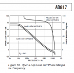
Actually, looking through my notes, I think the AD817 is somewhat of a sleeper here! It is specced down to single 5V, but can be used up to 30V, fast, high slew, available in DIL and not so expensive!
I would try that one for a 5V version.
Jan
Actually, looking through my notes, I think the AD817 is somewhat of a sleeper here! It is specced down to single 5V, but can be used up to 30V, fast, high slew, available in DIL and not so expensive!
I would try that one for a 5V version.
Jan
Last edited:
Thank you Jan.
Actually I did some search on the net about AD825, but came up only with couple of cases where it was tried at so low supply voltage. It was supposedly working, but there was no real measuring data. So I don't know how well working.
Thanks for a tip on AD817, I completely managed to miss it.
Actually I did some search on the net about AD825, but came up only with couple of cases where it was tried at so low supply voltage. It was supposedly working, but there was no real measuring data. So I don't know how well working.
Thanks for a tip on AD817, I completely managed to miss it.
")
I always suspected that the main reason people love the AD817 opamp for the Jung regulator, was that you couldn't ever get it to oscillate. Bad PCB layout? no problem. Poor choice of output capacitor(s)? no problem. Slow output-drive transistor? no problem. The enormously generous phase margin (> 80 degrees!) of the AD817, covers a multitude of sins.
Its nitromethane-fuelled uncle, the AD797, was difficult to stabilize, even for Walt Jung. Reaction: replace by an opamp that's easy to stabilize. Or so I imagined.
Its nitromethane-fuelled uncle, the AD797, was difficult to stabilize, even for Walt Jung. Reaction: replace by an opamp that's easy to stabilize. Or so I imagined.
Attachments
It doesn't always oscillate, and you can put some compensation around it -- but I found that the impedance with the AD797 could go lower than even what Walt showed in the 1995 articles!
In one instance I was able to get the local ABC AM station to excite the AD797 when it was not in its shielded box!
In one instance I was able to get the local ABC AM station to excite the AD797 when it was not in its shielded box!
I like the idea of using a preregulator (IF you've got the voltage headroom) simply as an enhancer of "line regulation", i.e., to reduce ripple at the input of the downstream, second voltage regulator. I'm not so enthusiastic about Walt Jung's bootstrap connection, in which the reference for the preregulator is connected to the final output of the second regulator. As far as I'm concerned, "ground" is always a less noisy reference than "Vout_final".
Consider: if the preregulator does its job, its output voltage will be constant. If the downstream voltage regulator does its job, that output voltage is also constant. Voila, the input-to-output voltage of the final regulator is constant. Without any bootstrap connection.
Some people on diyAudio are enthusiastic about using a series mode preregulator followed by a shunt mode final regulator. The series regulator sees a constant current load and the shunt regulator sees a constant voltage input. Nice!
A quick question for anyone. Is it still recommended to incorporate a pre-regulator?
The pre-regulator increases the Zout of the circuit in the low frequency zone, but Z out is lower thereafter.
Attachments
Last edited:
Is the layout with these boards critical to achieve the results in the graphs that were linked to?
Or can I build them on some Vero and they work just the same? Can I bunch up the components to make the board size smaller and have no degradation to performance? I'm in the UK and at £10 postage per board, or if I buy two or more, + 20% tax + £10 fee + £10 postage, they work out to be expensive.
To use the AD797 does the regulator have to go in a metal box? Is it best to not take the risk and use a 49710? Or 49990?
Instead of the large electrolytics, can I use some smaller polymer caps of maybe some 10uF X7R ceramics and maintain the same performance?
Is there a surface mount board version of these regulators so I can make them even smaller?
Are there a ready designed and tested ±5v and +3.3V versions that have similar performance figures?
Thanks.
Is the layout with these boards critical to achieve the results in the graphs that were linked to?
PAs SJOSTROM boards are in a somewhat different layout, and performed quite well. They also ranked high in the bake-off.
To use the AD797 does the regulator have to go in a metal box? Is it best to not take the risk and use a 49710? Or 49990?
I would shield the regulator if you use the AD797. I think you would certainly find the slower AD825 to work very well.
Instead of the large electrolytics, can I use some smaller polymer caps of maybe some 10uF X7R ceramics and maintain the same performance?
Do not use film caps where electrolytics are specified. Panasonic FC's work fine.
I like to place an RC stage before any regulator, to round off the sawtooth waveform and reduce upper harmonics. No use feeding any regulator all that stuff, less work for the error amp in it.
I think this is a very sensible suggestion. Anything that will make life of the reg easier, especially at higher frequencies, is worth while considering.
Jan
Thanks Jan. I have tried up to three RC stages of different values in series before the regulator, and there was only a few mv of ripple left for the regulator to deal with. There was almost pure DC feeding it by then, and it did seem to improve the sound. The nice thing about the RC vs an LC is that the RC is flatter thru the high frequencies and no ringing. An LC can give you peaks and valleys as you go higher in frequency, due to the C across the windings.
hirez69 said:Hi,
I would like to use your super regulator to supply +/-45V at around 1A-1,2A. is it possible to obtain such value adopting TI OPA445AP? if the answer is affermative, which is the BOM for this configuration?
sorry for my bad English
Best Regards
Vin
Hi Vin,
+/-45V should be OK with this opamp which can work with up to 90V supply.
Obviously you need to adapt the resistors that supply the current to the LM329 to keep approximately the same current as in the ususal 15V version.
Also change the ratio of the voltage divider on the -input to divide down your output voltage to the reference voltage of the '329.
I would also make sure you have a pass device with at least 100 Hfe to be sure you get enough output current with the current source at the base.
And don't forget to raise the capacitor working voltage to the new Vout + some safety margin.
Lastly, since the opamp is specced for max 15 mA Iout, the current source should be set to say 12mA to maximize Iout; with an Hfe of 100 that would be about 1.2A.
Edit: change the zener in the opamp output line to a value about half Vout to place the opamp output nicely in the middle of it's working range.
Your performance will not be exactly like the 15V version with an AD825 or 817, but should still be very good.
Jan
Last edited:
- Home
- The diyAudio Store
- Super Regulator