The Jung/Didden Super Regulator is a sophisticated, high performance, marginally stable circuit that is prone to oscillation, even when constructed by expert designers who have lots of experience. I recommend that you DON'T try to modify it unless you really know what you're doing.
If you can duplicate jackinnj's simulated Bode plot of the unmodified Super Regulator (in post#177), then you might have a chance of succeeding. If not, I recommend you don't attempt to modify the SR. It won't work and you'll be unhappy.
http://www.diyaudio.com/forums/blog...level-audio-part-vi-jung-super-regulator.html
Some of the resistors values in the above link are different from Jung SR 2000.
I have changed the resistor values according to SR 2000 version.
Other changes are :
replacing LT1086 by LT1084 (max current 4A);
R1 changed to 1.5k to get 12V output;
AD797 is used;
IRFP240 is used (for comparison with jack's result).
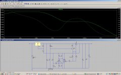
For ac analysis, instead of plotting Vout, 1/Vout is plotting so that the dB in the vertical axs is +ve.
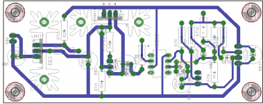
The schematic used for simulation is attached for verifivation.
Attachments
Last edited:
Finished my board..... is there a build thread
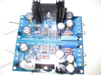
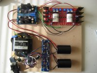
Some pics:
Tested them and regulation is real good, I can modify the input between 28 and 40 volts and the output stays exactly 24.00V. Also when loaded with a 220Ohm resistor, so around 100mA, output still is 24.00V.
I modified the V2.2 boards with a 5K trimpot at the R6 and R13 position. ( if you don't place the ceramic cap you have exactly a third hole for the trimpot ) The cer cap can then be placed at the bottom.
I intend to use these superregs for my BA-3 as a preamp which need + and - 24Volt.
I used a AD817 from Mouser.
Now have to complete the build and listen to it
Thanks Jan!
Attachments
Last edited:
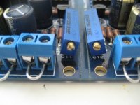
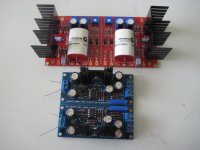
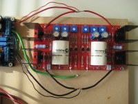
Some more pictures and questions....
Is this a right implementation of the sense wires? I sense just the V+ and V-
As you can see I had to couple the positive and negative regulator at the end of the PCB to create a common PSU ground to the BA3 board. Green wires. I included the sense in this common PSU ground.
Is there an other (better) way to do it?
I consider building another set of superregs so I can feed every rail of the BA3 board separately. 4 rails, 4 superregs. Will this enhance performance or at least channel separation?
Walter
Attachments
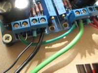
The only suggestion I have is to duplicate the green wire from the neg reg to the board, to the same point where the existing green wire goes.
Also then run the ground sense wires from each reg (which you now have jumped in the terminal blocks) to this same point, as you have done with the 'hot' sense wires.
The next step would be, as you say, to get another pair of regs.
Jan
Also then run the ground sense wires from each reg (which you now have jumped in the terminal blocks) to this same point, as you have done with the 'hot' sense wires.
The next step would be, as you say, to get another pair of regs.
Jan
My apologies if it is somewhere in the article or if it has already been asked and answered... I just couldn't find it. The heatsinks seem to be Fischer sk104, 35mmx12.7mm, with a 25.4mm spacing for the solder pins. Is that correct ?
And while I'm at it asking stupid questions: the Diyaudio store is the only source for those pcb, no European source for it, right?
And while I'm at it asking stupid questions: the Diyaudio store is the only source for those pcb, no European source for it, right?
BTW The SK104 comes in several lengths, iirc 25mm, 35mm, 50mm and 63mm.
For mostr small signal apps, the 25 or 35mm is fine. If you have more power to dissipate, go for the longer ones if you have the space above the PCB.
If you know the voltage across the pass transistor and the load current, multiply the two to get the dissipation in Watts.
The heatsinks have a parameter giving the temp rise per watt dissipation, looks like Rth = xx degree / Watt, like 10 degree / watt for some heatsink.
So if your dissipation is 7 watt, and the heatsink is 10 degrees/ W, the temp rise will be 7 x 10 = 70 degrees above ambient.
That is usually about the max you want to go, better is not to go above a temp rise of 30-40 degrees.
Jan
Last edited:
Yep. That much was clear. I'm pretty much stuck with the 25mm one anyway, since the case intended for the project is 1U (40mm high).
The 25mm high one is 14K/W. It should be ok, as I'm only looking for a drop of 7 to 8V at 0.2A, or about 1.5W per heatsink.
Thanks again for those new boards.
The 25mm high one is 14K/W. It should be ok, as I'm only looking for a drop of 7 to 8V at 0.2A, or about 1.5W per heatsink.
Thanks again for those new boards.
Euvl,
I am going to try your experimental HV reg in a Salas 6v6 preamp build. What kind of input voltage should I be looking at for an output voltage of 340V. I am unsure about the amount of dropout to allow for. Also, I assume that the ratio of R2/R3(6.9)is what determines the output voltage.
I am going to try your experimental HV reg in a Salas 6v6 preamp build. What kind of input voltage should I be looking at for an output voltage of 340V. I am unsure about the amount of dropout to allow for. Also, I assume that the ratio of R2/R3(6.9)is what determines the output voltage.
Buzz
it is usual to use a transformer voltage that equals the regulated output voltage. BUT !!!! this only applies over a small range of regulated voltage, i.e. ~9Vdc to ~25Vdc.
At lower voltages you need a bit extra AC supply voltage. At higher voltages you need a bit less, say 25Vdc to 50Vdc.
At very high voltage the general guidance falls apart.
You need to work it out.
I'll take a guess that a 115:280Vac transformer is suitable.
The range of supply voltage could be 108Vac to 126Vac.
Start with your lowest voltage.
The open circuit voltage from your transformer is:
Vpk = Vsupply/Vrated*Vsecondary*Transformer regulation*sqrt(2) -Diode drop
=[108/115*280*{1+8%/100}*1.414]-1.4~400Vpk
Will the 400Vpk be sufficient when the transformer is loaded to give sufficient Vdrop across the CCS and yield 350Vdc? Probably. As a second guess take off half the transformer regulation, i.e. remove 4% giving Vdrop = 384-350 = 34Vdrop.
Now look at the highest voltage which is available and must be acceptable to the regulator devices:
Vpk = Vsupply/Vrated*Vsecondary*Transformer regulation*sqrt(2) -Diode drop
=[126/115*280*{1+8%/100}*1.414]-1.4 ~467Vpk
The CCS must now drop 467 - 350 ~ 117Vdrop.
Calculate the power that must be dissipated in the CCS for this maximum supply voltage. Pmax = Vdrop* Iccs
Go and find out your numbers to put into the two equations.
You need YOUR numbers.
Last edited:
Thanks Andrew. I have 115 mains and happent to have a transformer with 300V secondaries, so i will try that just for the sake of availabilty. In this preamp, the CCS should dissipate about 3w, if my math is correct, as it will draw about 20mA per channel and I am going dual mono.
I appreciate the thorough explanation.
I appreciate the thorough explanation.
Also doing a positive version for a RIAA stage. I need 36V=/-, so I have made the following changes. t
opamp = LT-1792
d2=18V
r4=2.2K
r5=22K
r6=4.32k
All caps are 50V 120uF Panasonic FM. They have an ESR that is 1/4th of the FC. I assume this will not create a problem.
Also, I am using the LM317 as a prereg and wanted to know if the resistor combination needed to be changed. I assume that it follows the ouput voltage, but do not know hoe to calculate the setting resistors. It appears to set the voltage slightly higher than the ouput, but not sure.
Attachments
I need 36V=/-, so I have made the following changes.
One change you should consider is changing the opamp to something like an OPA604 -- it's a single with higher voltage capabilities.
Are you suggesting that it will perform better than the Lt1792. The Lt has better numbers, but only guarenteed at spec'd working voltages.
The OPA604/2604 are +/-24V, the LT1792 is +/-20V.
I have nothing against the LT1792, just have good results with the TI device. It might offer you a bit better protection against a high rail voltage.
There are high voltage opamps around (if I remember correctly from both LT & AD) that has excellent specs.
And the voltage headroom depends on the current consumption and the size of the cap after rectifier.
Do a sim on Spice. That will give you a better indication.
Patrick
And the voltage headroom depends on the current consumption and the size of the cap after rectifier.
Do a sim on Spice. That will give you a better indication.
Patrick
I am not good with Spice and at the moment, do not have the time to learn. If all looks good with the above changes, I will move forward with the OPA604. Thank you both.
Btw, Euvl. I will be giving a version of your F5X preamp a go. Using Toshiba instead of the lats you went with, simply because i have them. Sorry for OT.
Btw, Euvl. I will be giving a version of your F5X preamp a go. Using Toshiba instead of the lats you went with, simply because i have them. Sorry for OT.
Last edited:
- Home
- The diyAudio Store
- Super Regulator