Please read my post. Do you understand what I am trying to say? Pencil in the voltages in the schematic. If you use a 6.9V ref, the bottom 1k resistor obviously has 6.9V across it. What is then the voltage across the top resistor?
The voltage across the top resistor has to be 30v minus 6.2v, 23.8v, which seems to get me a 3K9 value for the top resistor. That gets me 6.2v in +in and -in.
The voltage across the top resistor has to be 30v minus 6.2v, 23.8v,
Bingo! Almost. The ref diode is 6.9V, not 6.2V. So you get 23.1V across the top resistor.
23.8v, which seems to get me a 3K9 value for the top resistor.
How so?
Jan
Walt Jung invented the GLED431 for exactly this purpose: to create a shunt voltage reference circuit with the lowest possible noise. Although the diyAudio search is unable to find it (try the experiment if you don't believe me), Google succeeds
Mr. Jung's ultra-low noise VREF - the GLED431
Full and complete .pdf attached to post #56 of that thread
You will need to do some arithmetic to use it in a Super Regulator, since the low low LOW noise reference voltage it produces, is not equal to the reference voltage produced by an LM329. But DIYers are clever, crafty, and resourceful!
_
Last edited:
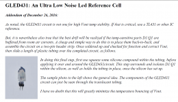
More on tweaking the GLED431 2.5v ref
While I do appreciate Mark Johnson’s comments on the GLED431 circuit and the very low noise it can achieve, I could not find the writeup with the thermal shield addendum. But for sure it can be found on my website:
https://refsnregs.waltjung.org/GLED...D Reference Cell _Walt's Blog 2014_092418.pdf
The lowest noise will be found when the circuit is fed with ample source current, i.e., 8mA or perhaps more. This is to ensure that the PNP is really running with at least 4mA of current.
Since the original setup with the 3mm thruhole GLED, I have built versions with a Liteon SMD equivalent diode. They worked virtually identical to the leaded LED versions. Agonizing to fit to a pcb, but great once soldered in place.
Also, a ZTX550 works well as the amplifier, and is slightly cheaper vs. the 951. Both are Diodes Inc. parts.
Walt Jung invented the GLED431 for exactly this purpose: to create a shunt voltage reference circuit with the lowest possible noise. Although the diyAudio search is unable to find it (try the experiment if you don't believe me), Google succeeds
Mr. Jung's ultra-low noise VREF - the GLED431
Full and complete .pdf attached to post #56 of that thread
You will need to do some arithmetic to use it in a Super Regulator, since the low low LOW noise reference voltage it produces, is not equal to the reference voltage produced by an LM329. But DIYers are clever, crafty, and resourceful!
_
While I do appreciate Mark Johnson’s comments on the GLED431 circuit and the very low noise it can achieve, I could not find the writeup with the thermal shield addendum. But for sure it can be found on my website:
https://refsnregs.waltjung.org/GLED...D Reference Cell _Walt's Blog 2014_092418.pdf
The lowest noise will be found when the circuit is fed with ample source current, i.e., 8mA or perhaps more. This is to ensure that the PNP is really running with at least 4mA of current.
Since the original setup with the 3mm thruhole GLED, I have built versions with a Liteon SMD equivalent diode. They worked virtually identical to the leaded LED versions. Agonizing to fit to a pcb, but great once soldered in place.
Also, a ZTX550 works well as the amplifier, and is slightly cheaper vs. the 951. Both are Diodes Inc. parts.
Here's the .pdf attachment from post #56 ... and if you look closely, you'll see that post #56 was written by Walt himself!
https://www.diyaudio.com/forums/att...-reference-cell-_walts-blog-2014_092418_r-pdf
This .pdf is two and a half pages long; when I zoom way out to get the whole thing on my screen, it looks like Figure 1 below. When I view only the final page, I see something that looks like Figure 2 below. I *think* this is the thermal addendum but I could be mistaken.
_
Attachments
Yeah pour choice of words... I meant parallel to each other... In series outputs makes more sense as a sentence
Isolated PSUs? I was thinking dual secondaries. So I just do not connect the raw supplies at the prefilters? Just run them in parallel and connect just the outputs of the regs to form the common 0V reference?
Perhaps one more hidden advantage: The NPNs have mostly higher early voltage than PNPs, which will increase the PSRR performance IMO
And yeah, two positive supply simplifies BOM as well.

The series pass transistor is contained within the negative feedback loop and so any errors introduced by its Early voltage, are reduced by NFB in exactly the same way that all other in-loop errors are reduced by NFB.
For those who are enthralled by Early voltage of power PNP transistors, allow me to present the Sanken 2SA2223 sold by DigiKey and listed by octopart.com. Early voltage is about 550 volts. That's a big number.
_
For those who are enthralled by Early voltage of power PNP transistors, allow me to present the Sanken 2SA2223 sold by DigiKey and listed by octopart.com. Early voltage is about 550 volts. That's a big number.
_
Attachments
The series pass transistor is contained within the negative feedback loop and so any errors introduced by its Early voltage, are reduced by NFB in exactly the same way that all other in-loop errors are reduced by NFB.
For those who are enthralled by Early voltage of power PNP transistors, allow me to present the Sanken 2SA2223 sold by DigiKey and listed by octopart.com. Early voltage is about 550 volts. That's a big number.
_
Ahh, transistor tracer from lockyz! I used that to check "used" LM394 and MAT12s from electronic trash vendors. Merely by mentioning the curve tracer could scare away those selling counterfeits. That 100 some dollar worth every cent of it.
To the early voltage thing. My speculation is that, when harmonics with frequency higher than the effective bandwidth of error amp are being injected into the regulator, one could still get some degree of attenuation with the flatter Vce-Ic characteristic of pass element. For example, at one time point the load current can be viewed as constant (Also the base current), because musics are of course slower than EMI. Then, interference cause Vce to rise, but the Ic should remain relatively unchanged, which again prevents the output voltage from swinging..
Of course, capacitive coupling via junction capacitance is not considered here. Perhaps cascoding the pass element to reduce effective Cce? Saw that once in LISA3 Headamp.
Hi,
Looking this board seems on the PCB is not present a GDN plane. There is any reason about this choice? Normally it's suggested to develop the boards with a GDN plane to avoid noise etc.. it isn't?
I have to put before this regulator a bridge rectifier, my load will be of about 250/500mA. A capacitor value after the rectifier bridge of 2200uf is enough to a have a good result?
Thank you
ps: there is any way to increase the current capabilities to 3A?
No ground plane. Gnd planes can help to screen against external noise in sensitive circuits, but the disadvantage is that you have little control over where the currents flow. In the SuperReg ground routing is very important so I decided no Gnd plane, this time; my first board for Audio Amateur did have a ground plane. I didn't see any advantage.
A 2200uF cap discharges between charging pulses at 50 (or 60) Hz frequency. Assuming a current of 500mA, and a discharge time of 8ms, it discharges by (500mA * 8ms)/2200uF is about 40/22 or about 1.8V, so that would be your pk-pk ripple. If you have enough head room for the regulator it will be fine. Note that bigger caps cause sharper ripples with higher frequency junk, so don't overdo it.
Higher current: this setup is limited to about 1A. Some people here said they tried using a Darlington as pass device, but I haven't seen any feedback from that.
Jan
Last edited:
No ground plane. Gnd planes can help to screen against external noise in sensitive circuits, but the disadvantage is that you have little control over where the currents flow. In the SuperReg ground routing is very important so I decided no Gnd plane, this time; my first board for Audio Amateur did have a ground plane. I didn't see any advantage.
What about the advantages or disadvantages of making trails wider/thicker instead of thin?
In the SuperReg ground routing is very important so I decided no Gnd plane, this time; my first board for Audio Amateur did have a ground plane. I didn't see any advantage.
Jan
Attachments
I see an advantage in using 2 oz (70 microns thick) copper compared to 1 oz (35 microns thick) copper. Even on not-exactly-super regulator PCBs like VRDN. So I pay extra for 2 oz and I pay extra again for ENIG.
I am not talking about using thicker copper pcb, but widening the tracks. Say go from 1mm or 2mm, up to 3, 4 or more millimeters. Really wide.
What are the problems against that?
- Home
- The diyAudio Store
- Super Regulator