Check if the existing Power Resistors are in series, or in parallel.
If in series you can replace the Power Resistors with Power Thermistors.
If in parallel, you can only use one Power Thermistor to replace the resistors.
Don't use NTC Power Thermistors in a parallel configuration.
If in series you can replace the Power Resistors with Power Thermistors.
If in parallel, you can only use one Power Thermistor to replace the resistors.
Don't use NTC Power Thermistors in a parallel configuration.
No. For 120v AC, a minimum rating of 200V would be appropriate.
That said, there is essentially no difference in price between a 1N4001 (50V) and a 1N4007 (1000V)
I forgot to include 1N4007 in my Mouser order however have some 1N4001 laying around, thus the question. Thank you for your answers!
I've decided that life is too short to use cheap and feeble diodes any more; I've decided that it's penny wise and pound foolish to fool with 1 amp diodes when 3-6 amp diodes are available at reasonable cost. So for axial-lead applications I keep a drawer full of UF5408s (3A, 1000V) and MUR460s (4A, 600V). For TO-220 diodes I reach for my drawer full of MUR1520s (15A, 200V) and FES16JTs (16A, 600V). When a bridge assembly is needed, I pay up for the GBPC5010 (50A, 1000V). Kill a fly with a bazooka; bazookas are reasonably priced.
for 120Vac one should use a bridge rectifier rated for 360Vac. i.e. >=three times the AC voltage.
The individual diodes need a reverse voltage rating of >1.5times the AC voltage.
Good advice, I wasn't sure there was a succinct rule of thumb. Thank you!
I've decided that life is too short to use cheap and feeble diodes any more; I've decided that it's penny wise and pound foolish to fool with 1 amp diodes when 3-6 amp diodes are available at reasonable cost. ..snip... Kill a fly with a bazooka; bazookas are reasonably priced.
A sound plan of attack!
What would be the effect of replacing the R3-R6 resistors with a CL-60? Will it make the board safer to operate (e.g in case of relay failure)?
Noob question: what does CL-60 mean?
The cl60 is a negative temperature coefficient thermistor.
Most things have a positive temperature coefficient so if you take a light bulb filament for example, as it gets hot the resistance goes up. With a ntc the resistance goes goes down. So on power up the cl60 provides some resistance and after a few seconds (look at the Datasheet for accurate figures) it gets hot and then the resistance drops effectively disappearing from the circuit (to a point, depends whether enough current is going through it.)
Most things have a positive temperature coefficient so if you take a light bulb filament for example, as it gets hot the resistance goes up. With a ntc the resistance goes goes down. So on power up the cl60 provides some resistance and after a few seconds (look at the Datasheet for accurate figures) it gets hot and then the resistance drops effectively disappearing from the circuit (to a point, depends whether enough current is going through it.)
What would be the effect of replacing the R3-R6 resistors with a CL-60? Will it make the board safer to operate (e.g in case of relay failure)?
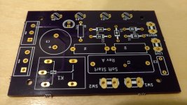
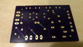
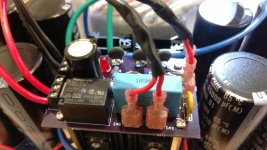
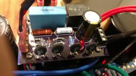
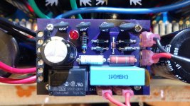
I have 2 left over boards for the Soft Start with room for 4 CL-60 thermistors serially connected instead of 4 power resistors as in the original board. The rest of the schematics is the same and the PCB uses the same BOM as the one sold in the store (except for external connectors - see the pictures). I will sell these at cost ($12 + shipping). Please PM if interested.
Here are pictures of the board (before I assembled it and after) mounted on top of the Universal PSU. The PCB dimension is the same as one section of the Universal PSU with rectifiers (55mm by 75mm) and mount holes are drilled at 40mm by 60mm to match those in the Universal PSU. Selling boards only, not the parts. Usual legal disclaimers apply.
Attachments
Hello, I see here that C1 (C9 on the link) must be 0.01uF 250VAC Y1 capacitor.
On the V3 version in BOM I read 0.01uF 1KV Radial Ceramic.
1) Why and which use ?
2) I read on this reply on this post
"C1 is in the wrong place.
As shown it bypasses the switch, so that you can never switch off your equipment !"
Who is right/wrong ?
Thanks !
On the V3 version in BOM I read 0.01uF 1KV Radial Ceramic.
1) Why and which use ?
2) I read on this reply on this post
"C1 is in the wrong place.
As shown it bypasses the switch, so that you can never switch off your equipment !"
Who is right/wrong ?
Thanks !
C9 and C11 must be rated for mains use. X1 or X2 when between Live and neutral, Y1 or Y2 when live to protective earth or Neutral to protective Earth.Hello, I see here that C1 (C9 on the link) must be 0.01uF 250VAC Y1 capacitor.
DO NOT use non mains rated capacitors on the mains.On the V3 version in BOM I read 0.01uF 1KV Radial Ceramic.
Can I be biased and state that I must be right. Because I read it on the internet...................
2) I read on this reply on this post
"C1 is in the wrong place.
As shown it bypasses the switch, so that you can never switch off your equipment !"
.............
But just look at what the switch + parallel capacitor does.
They are in parallel !
One bypasses the other.
If only one is active then mains current will pass through !
Is that not obvious?
And that prompts my final comments.
If you can't see that, then you are not competent to work with mains electricity.
Until you have learned how to correctly and safely wire up mains power get some competent help, at least to look over your shoulder.
Last edited:
I have read the whole post and many diagrams and pics are missing. My ? Is proper hook up to power. I have 120 wall power to the switch that came from the Diy store with case kit after the switch the ground is wired to the case bottom making a star ground which is also wired to ground of the universal psu then one of the hot wires connects to neutral the other hot wire to live/sw1 on the soft start is this correct. And what is sw2 for?
Hello, I see here that C1 (C9 on the link) must be 0.01uF 250VAC Y1 capacitor.
On the V3 version in BOM I read 0.01uF 1KV Radial Ceramic.
1) Why and which use ?
2) I read on this reply on this post
"C1 is in the wrong place.
As shown it bypasses the switch, so that you can never switch off your equipment !"
Who is right/wrong ?
Thanks !
i will place Ci right at the switch contacts, it is used to suppress the arcing of switch contacts when the switch is turned off. i use disk ceramic caps rated for 2kv, but 1 kv is also fine, not more than 0.01ufd or else you may find that even when switched off, your led panel lights may still be on..
mains rated caps are so called because of their self healing properties, the caps themselves have no idea where they are used in, as long as dielectric breakdowns are never exceeded, they will just be fine...
i even used those mains rated caps as coupling caps in a tube amp and no one can tell the difference...
capacitor safety mandates the use of properly voltage rated caps...
Delaying switching time
Hi All,
I just tested my softstart boards (1 x V2 and 1 x V3), both are fitted the same.
C2 = 220nF X2 275V
C3 = 1000uF 50V
R1 = 220R 3W
R2 = 1M 3W
I am on 240V mains, with C2 = 220nF the relay never turns on. I increased C2 to 330nF and it works like a charm, but I find the delay somewhat short... I'd say less than 1/2 second.
Testing is without load, i.e. no transformer, no PSU/Caps.
I could try to trigger the delay on scope to have exact figures.
Will the delay change under load ? Should I test with at least Xformer and next step with PSU ?
Increasing C3 should give a longer delay , no ?
Thanks all in advance for your input !
Cheers,
Max
1/2 second is about right. It's enough to keep the inrush current limited when the filter capacitors are empty and appear a dead short. Just a bit of charge makes the inrush quite a lot less.
The other neat trick you can do on this board is run the LED really bright - or better yet, use a higher current LED - as the location of the LED drains the capacitor during it's charge period, the brighter the LED (because brightness is controlled by current) the more delay you can add.
The other neat trick you can do on this board is run the LED really bright - or better yet, use a higher current LED - as the location of the LED drains the capacitor during it's charge period, the brighter the LED (because brightness is controlled by current) the more delay you can add.
- Home
- The diyAudio Store
- Power Supply Soft Start Board (V3)