In reading a build guide that says it's OK to use 25V caps, even with 24VDC? That that is what the actual FW amps use?. I thought the rule of thumb was to double the actual volts to determine cap ratings. Don't get me wrong, I'd be happy to abandon 50V and use less expensive caps (our higher uF).
Also, what gauge wire do people use? My main experiences are with low current circuits so it never came up.
-david
Also, what gauge wire do people use? My main experiences are with low current circuits so it never came up.
-david
Bones, Rif, Alarudin -
This webpage has lots of great information on amplifier power supplies - big picture ideas as well as good information on the small details. Although supposedly about chipamp PSU, all the ideas carry over to bigger amps.
Building a Gainclone chip amp power supply.
This webpage has lots of great information on amplifier power supplies - big picture ideas as well as good information on the small details. Although supposedly about chipamp PSU, all the ideas carry over to bigger amps.
Building a Gainclone chip amp power supply.
2 bridges - positive and negative rails. This board set makes for a positive line, negative line and ground.
I don't know that the V+++ terminology, unless its just V+ 1, 2, and 3. Only one voltage comes out at a time, mainly depending on the secondary voltage of the transformer.
I am planning Aleph J as well, its 2x 18volt secondaries from the transformer to this board, to make the 24 volts V+, V-, and ground needed for this amp.
I plugged the values 18v, rectifier, 30uF, 0.1R, 3uF into PSUD2 and got very close to the 24v needed. I plan to use the bleeder resistors of course, and the output snubber.
Hey Bones13, was curious how you got your values for input snubber resistor and input snubber capacitor? Note 4 links to an article which is way over my head.
I am trying to purchase parts for F4 stereo build. I have the new v3 pcb on the way and will be using bridge rectifier instead of the rectifier board.
Thanks
Heh, one of the reasons I am omitting the input snubber is that I can't make heads or tails of the snubber article myself. The values for the output is on the BOM.
I did get a scope, and plan to have a look at what my eventual PSU looks like.
Thanks for the link 6L6 ! Learning is all part of the process for me.
So far I have ordered the V3 universal PSU boards, and the soft start board. I ordered an AnTek 500 VA 18/18 transformer (the 400 ones are still MIA). I also have received the push button circuit, and transformer board from AMB, so that I can have a push momentary contact On/Off switch up front. (its down to green/red/blue...)
Currently building the ACA, and slowly plotting a BOM at Mouser for the Aleph J. Need to learn a few more things, but with the nice boards and support here, worlds easier than trying to create it all by myself. (and lots safer too, I imagine)
Last edited:
I am building a V3 power supply with 45V rails and would like to use eight 20000-27000uf 63V caps. However, all of these are 40mm diameter. Will these new PSU boards be able to accomodate this size? I feel that with 45V rails I would feel more comfortable with 63V caps vs 50V caps.
Thanks.
Thanks.
40mm won't fit. I am just building a set of v3's with dual 45v tranfos, to get 63v rails. These are the caps I chose. There aren't many options available.
ESMH800VNN103MA50T - UNITED CHEMI-CON - CAPACITOR ALUM ELEC 10000UF 80V | Newark
ESMH800VNN103MA50T - UNITED CHEMI-CON - CAPACITOR ALUM ELEC 10000UF 80V | Newark
Just use 50V caps.
I was thinking of using the Antek AN-8234 transformers. 34V times 1.414=48V at the rails unloaded, so loaded around 45V.
Panasonic ECE-T1HA273EA, 27000uf 50V 105C, specs say 50V working voltage 63V surge. These have 4 pins. Don't the store boards have only 2 holes?
Thanks.
Nash
Try these - ECO-S1HP223EA Panasonic | Mouser
Thanks. And at $7.21 at Mouser a lot less expensive too! Looks like the difference between the Panasonic TSUP and TUP series is that the former has two pins while the latter has 4 pins. Both are 85C rated and seem to have identical specs otherwise. The THA has 4 pins and is 105C rated with somewhat better specs.
Any subjective opinions between these three Panasonic series caps?
Yes.
The 4-pin won't fit, so I wouldn't use them. The 105c rated caps may be better, but they might not. They will, most likely, last longer as they are a higher temp rating.
In general, however, don't worry about it. Buy ones that are of the value you need/want, and that fit the PCB.
The 4-pin won't fit, so I wouldn't use them. The 105c rated caps may be better, but they might not. They will, most likely, last longer as they are a higher temp rating.
In general, however, don't worry about it. Buy ones that are of the value you need/want, and that fit the PCB.
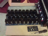
Finished my v3 boards for my Honey Badger. These boards are great, 35mm caps fit with no problems. I did have to find shorter bolts for the heat sink mount kits as the ones in the kit don't fit when back to back, but that's no issue. I could have cut them shorter too.
Attachments
Yes, but he needs the practice.")
good quality time! i love it.
geting him hooked early.
This may have been asked before, my apologies.
Looking at the (+) side only, do c3 and c4 have to be equal? Same for C7 and c8?
For example if I had 2 10kuF 50v caps and 22kuF 35v caps, could the CRC filter go: 10kuF + 22kuF, then resistors, then 10kuF + 22kuF? Or should same kuF caps stay together, creating an imbalance between the sides?
The various caps would be Panasonic ts-up, the main difference are kuF and volts.
The (-) would mirror this arrangement.
Thanks
filter caps max voltage
Thank you for all the answers, had a much better understanding of the board now. Just a quick question. From reading other posts, 20% seem to be the safe buffer for choosing caps max voltage.
40vac X 1.414 = 56.56 vdc so 20% will bring it to 67.872 vdc (some site mention another -2v for rectifier material etc?)
But I have some leftovers of 63v tsha caps. Will it work? Thier working temp is at 105 degree max as oppose to the 85 degree version.
Or should I just stop being a cheapo and buy another traffo with 35 vac secondary.
Lastly, will there be a difference of sound quality if I choose 40 vac over 35 vac secondary. (honey badger's recommended is 45vac secondary) or should I stick to 40vac and buy a new set of filter caps.
Appreciate help from experience builders! Thank you.
Regards,
Askae
There is a discussion about this right now on the Honey Badger build thread. Start with this post and read forward. http://www.diyaudio.com/forums/soli...honey-badger-build-thread-59.html#post3626049 It appears 63v rails, or 45v secondaries, produces much better sound than 37v rails.
I think 40 VAC and 63V caps is fine. I'm building a couple of amps doing just that. Others will disagree. With low load like an idling Badger you can expect a volt or two more due to transformer regulation then add another 5% for line voltage variation. Notice how close 40 VAC can get you to 63VDC?
Running close to ratings will probably will affect life but since nothing I build doesn't get upgraded within cap lifetimes...
Running close to ratings will probably will affect life but since nothing I build doesn't get upgraded within cap lifetimes...
The extra margin in choosing capacitor working voltage is for safety and reliability. I think 40VAC and with a stable line would work with 63VDC caps. That is if you already have the caps, but if you are to buy them then why not go one step higher for peace of mind.
Cheers
Cheers
- Home
- The diyAudio Store
- V3 Universal Power Supply Circuit Board