Working through my PSU, when using PSUD, what is a good value to use for the load for an Aleph J? Just stick with the 5KR that is the default?
Has anyone got some nominal values to use for the input snubbers? Or best left alone unless there is a problem?
(I am looking for 24v rails, and will use 15,000uF caps, and thinking 5x 0.47R for the CRC)
Lastly, advantages of the schottky diodes vs a rectifier bridge ?
Has anyone got some nominal values to use for the input snubbers? Or best left alone unless there is a problem?
(I am looking for 24v rails, and will use 15,000uF caps, and thinking 5x 0.47R for the CRC)
Lastly, advantages of the schottky diodes vs a rectifier bridge ?
It's one of those odd conventions that we mark the positive side on the board and the negative side on the cap. Makes me wonder if someone created the convention to protect his job every time I stuff a cap into a board. At least leaded caps have the positive lead longer...
You can find the build guide for the earlier rev of these boards at http://www.diyaudio.com/forums/diya...psu-capacitor-diode-combination-board-v2.html. It got me started but I'm stumped on a couple things too.
I'll be building an aleph J and have a few questions on the PS I've been collecting over the past week:
1) From the BOM, I'm not familiar with the dual diode devices. I've looked at the schematic for the PSU, and can't figure out if: both diodes in the pkg are used in parallel, both used independently, or if one just isn't used.
2) On the Pass schematics, are those thermistors? Any advice on what part to choose (digikey) would be appreciated.
3) Capacitors. I'm not knowledgeable enough to choose between: Panasonic TS-UP and TS-HA or Cornell Dubilier 380LX, 381LX, or SLPX. Or have I removed something from my short list I shouldn't have. (15000uF or 22000uF if affordable).
thanks
-david
Information needed
I believe the intention to have two bridges was to allow the board to be used for dual channel with a dedicated bridge for each channel. Correct me if im wrong.
However, im not 100% sure on how the connection was to be made if the board was to be in dual mono configuration with 2 x psu board being used. From my understanding of JoJo's build guide, we need to use jumper to join the 2 sets of board together. Manage to somehow figure out the way to connect the 2 boards up by carefully examining JoJo's final picture wth everything wired up (Magnifying the picture helps! ). Unfortunately the front part where the output connection to amp and grounding part where it show the star grounding is block by the front chassis panel! A picture speaks a thousand words really applies here, as i figured out quite alot of information through the final assembled picture.
Unfortunately the board JoJo used in the guide is a older version where all the ground are connected to a single output. With the newest version of the board, all the grounding are stand alone which allows for star grounding configuration which will suit advance users but confuse the hell outta newbies (like me) So maybe someone will give us some advice on how to actually use the new grounding scheme to our advantage.
Will need information on the following:
ST_IN(1-4)
ST_V+
ST_V-
ST_G1 & G2
GND 2.2
V+++ V++ V+, V--- V-- V-, GND GND1 GND2 <-- Do we just connect to anyone of them? Is the multiple holes meant for jumpering between boards?
Sorry for the dumb novice questions, but i believe there are someone like me in the world with limited background in Amplifier construction or design(although im a electronic student ) who just gotten the board shipped to us and found ourselves stuck with the vast number of connection options available to us.
Thank you!
SK
That makes sense. Not sure what the advantage of two bridges is though. I appreciate your assistance.
I believe the intention to have two bridges was to allow the board to be used for dual channel with a dedicated bridge for each channel. Correct me if im wrong.
However, im not 100% sure on how the connection was to be made if the board was to be in dual mono configuration with 2 x psu board being used. From my understanding of JoJo's build guide, we need to use jumper to join the 2 sets of board together. Manage to somehow figure out the way to connect the 2 boards up by carefully examining JoJo's final picture wth everything wired up (Magnifying the picture helps!
). Unfortunately the front part where the output connection to amp and grounding part where it show the star grounding is block by the front chassis panel! A picture speaks a thousand words really applies here, as i figured out quite alot of information through the final assembled picture. Unfortunately the board JoJo used in the guide is a older version where all the ground are connected to a single output. With the newest version of the board, all the grounding are stand alone which allows for star grounding configuration which will suit advance users but confuse the hell outta newbies (like me
) So maybe someone will give us some advice on how to actually use the new grounding scheme to our advantage. Will need information on the following:
ST_IN(1-4)
ST_V+
ST_V-
ST_G1 & G2
GND 2.2
V+++ V++ V+, V--- V-- V-, GND GND1 GND2 <-- Do we just connect to anyone of them? Is the multiple holes meant for jumpering between boards?
Sorry for the dumb novice questions, but i believe there are someone like me in the world with limited background in Amplifier construction or design(although im a electronic student
) who just gotten the board shipped to us and found ourselves stuck with the vast number of connection options available to us. Thank you!
SK
Last edited:
2 bridges - positive and negative rails. This board set makes for a positive line, negative line and ground.
I don't know that the V+++ terminology, unless its just V+ 1, 2, and 3. Only one voltage comes out at a time, mainly depending on the secondary voltage of the transformer.
I am planning Aleph J as well, its 2x 18volt secondaries from the transformer to this board, to make the 24 volts V+, V-, and ground needed for this amp.
I plugged the values 18v, rectifier, 30uF, 0.1R, 3uF into PSUD2 and got very close to the 24v needed. I plan to use the bleeder resistors of course, and the output snubber.
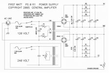
I am about to build an amp using the universal PS board. The schematic is giving me tired head. Why are there two bridges on the board, and what are the ST_ connections for?
There are two bridges, among other reasons to allow the positive and negative supplies to be used independently. There are schools of thought that favor the use of dual bridges and those that argue against it. If you want, you can use just one bridge for both rails, but you have to know what to do with the center tap.
It looks to me like the ST connections are set up to allow daisy chaining capacitor boards to make a CCRCCRCCRCC etc. filter. ST_G1 and ST_G2 seem like they are intended to connect to the star ground.
I'll be building an aleph J and have a few questions on the PS I've been collecting over the past week:
1) From the BOM, I'm not familiar with the dual diode devices. I've looked at the schematic for the PSU, and can't figure out if: both diodes in the pkg are used in parallel, both used independently, or if one just isn't used.
It's a little sideways but both cathodes are connected and both anodes are connected. They are used in parallel.
Yes, he uses CL30 a lot.2) On the Pass schematics, are those thermistors? Any advice on what part to choose (digikey) would be appreciated.
Any of those are fine. You'll get slighly longer life using the 105 degree versions.3) Capacitors. I'm not knowledgeable enough to choose between: Panasonic TS-UP and TS-HA or Cornell Dubilier 380LX, 381LX, or SLPX. Or have I removed something from my short list I shouldn't have. (15000uF or 22000uF if affordable).
thanks
-david
I believe the intention to have two bridges was to allow the board to be used for dual channel with a dedicated bridge for each channel. Correct me if im wrong.
However, im not 100% sure on how the connection was to be made if the board was to be in dual mono configuration with 2 x psu board being used. From my understanding of JoJo's build guide, we need to use jumper to join the 2 sets of board together. ... So maybe someone will give us some advice on how to actually use the new grounding scheme to our advantage.
For dual mono, connect one of the ground terminals from each PSU board to your main star ground. Other options exist, but that's as good a starting place as any.
Will need information on the following:
ST_IN(1-4)
ST_V+
ST_V-
ST_G1 & G2
GND 2.2
V+++ V++ V+, V--- V-- V-, GND GND1 GND2 <-- Do we just connect to anyone of them? Is the multiple holes meant for jumpering between boards?
Multiple holes to connect multiple loads. Notice that on the output side there are 4 groups of connections. all are the same, it doesn't matter unless you are lining up filter boards to make a more advanced filter. On the input side of the filter board you also have several connection options. In the basic mode, you should connect the V+1 to D+1 (see how they line up?) V-1 to D-1, etc. You don't need to connect V++1 to D++1, etc. if you use a heavy enough connection at V+1, but it won't hurt.
The only dumb questions are those not asked.Sorry for the dumb novice questions, ...
Hi,
May i check if there will be a build guide for V3 Universal Power Supply Circuit Board just like the other offered board? Having some problem understanding the multiple input options available. Thank you.
We'll eventually have a build guide, but it won't be for a while.
I am about to build an amp using the universal PS board. The schematic is giving me tired head. Why are there two bridges on the board, and what are the ST_ connections for?
I believe they are intended for stacking multiple PSU boards on top of each other.
You can find the build guide for the earlier rev of these boards at http://www.diyaudio.com/forums/diya...psu-capacitor-diode-combination-board-v2.html. It got me started but I'm stumped on a couple things too.
I'll see if I can get Jojo to chime in and respond to these questions. It's normal with a totally new board to have lots of questions, and we know the documentation is thin on the ground currently so fire away with your questions
- Home
- The diyAudio Store
- V3 Universal Power Supply Circuit Board