When you buy taps be sure to get bottoming taps. Most of the hardware store variety taps are for through holes. An industrial supply house would be a good bet or McMaster.com
I used McMaster p/n 8305A515, which is a set of three including taper, plug and bottoming type. Easier to start the threads with the tapered type and go back with the bottoming type. Also got the recommended drill bit to make the hole. I plan to use lots of clamping force, so I want good threads all the way down.
BK
I have had my Deluxe 4U chassis for a couple of weeks and just started to play around with it. For the most part it is very nice but there appear to be some significant QA issues with the one I received that are not apparent until you look at it very carefully.
First up - thanks for your purchase
")
Secondly, I'll just jump straight in and say that I'm guessing none of your issues appear to be QA issues (product defects, wrong parts put in the box, etc). Rather, misconfiguration on our part. Hifi2000 QA is impeccable - in the entire history of dealing with them the only error we've seen has been one amp camp amp heatsink mis-drilled and they have immediately shipped a replacement directly to the customer. However, mistakes do happen, and our promise is to fix them as quickly as possible when they do happen.
The reason for your issues are varied, and so I will address them here now..
1. The heat sinks do not have all of the holes that are shown in the specification for a Deluxe 4U and each heat sink is missing 3 holes. Did the specification change or is this a defect? Fortunately I don't need any of these holes for my project but it might affect someone else so heads up.
The 4U has 23 holes and the 5U has 26 holes (please refer to the specification). I'm going out on a limb to assume this is the missing 3 you are talking about. The specification has not changed since the very first production run.
http://www.diyaudio.com/forums/imag...sal/universal-mounting-specification-v2.1.pdf
If there are really 3 missing holes, and this isn't a confusion about the specification, things do go wrong sometimes and of course if you are missing a hole we will send you out a replacement immediately. Just send a photo to support and they'll arrange a replacement for you.
For your interest, the reason why there is a different hole spec for the 4U and 5U is as follows:
- The 4U is 300mm deep and the 5U is 400mm deep. Having those extra 4 holes in a 4U was deemed to be "over the top" considering the heatsinking on a 4U and would an extremely rare use-case for the 4U chassis, so we don't include them in order to keep the price as low as possible.
- The 4U has an extra hole for a Vbe multiplier transistor that the 5U does not - it's something used by projects with lower heatsinking requirements like class-ABs. The 5U is made of 2 x 200mm Heatsinks with a split in the middle. It wouldn't made sense to put a hole directly in the middle of the split, and most people making projects requiring that hole will be using 4U chassis because 5U would be over-the-top, so we left it out of the specification for the 400mm deep 5U chassis.
2. At least two of the holes (Ones that I need for my project) in one heat sink are not fully tapped or are not deep enough and the M3 standoffs from the parts kit don't screw in all the way. All the other holes I checked seem OK.
The minimum thread depth for the blind holes is 5mm and this is the specification to which Hifi2000 have always done it.
When we ordered the standoffs for the parts pack we just got "M3 standoffs" (actually at the time we didn't know how deep the heatsink threads were other than "deep enough"!). Mark received these and thought the fact they stood out 1mm was just fine because all his holes must have been tapped exactly the same length so everything was identical. For the next parts pack we'll get 4mm deep threaded M3 standoffs and I will send you out a set as soon as we have a source for them.
This is the first time anyone has mentioned that this is an issue to us - but I can imagine you thinking something must have gone wrong with QA. That's not the case - it's just that we thought that was good enough. The next batch of standoffs will all sit flat.
So, your feedback here is really important. We're talking about a very small, boutique product that we don't sell very many of and your constructive criticism to get it "perfect" is really appreciated.
3. None of the holes in the front panel are tapped.
I am going to assume you got a chassis from the previous run. In that case (and you can check) the perforated base should also have 12x10.5mm holes instead of our new standard of 10x10mm.
I don't know how that would have happened, because I thought we'd sold out of the previous run. We didn't change the SKU (stupid mistake really - we should always change the SKU even for minor changes). There is a chance they had an older chassis sitting on the shelves that was not in the system and that got sent out.
Now, if you have a 10x10 base AND there are no holes in the front panel, that would by a QA issue, in which case I will send you out a new front panel immediately.
The hole tapping issue is not a deal breaker since I can run down to the hardware store and pick up a tap. However it is a minor disappointment and is something that should be corrected in the future. This is something that should never have been allowed to leave the factory.
As stated above - I think you have confused the 4U and 5U specifications, but if it's really missing 3 holes I'll get you a replacement ASAP.
As has been pointed out by others the screws for the bottom internal base panel are too short to mount the panel "upside down". Easy to fix. But I would like to point out that all of the drawings of possible internal layouts for the Deluxe 4U on the store web site show the panel "upside down". On the other hand the photo of the Deluxe 4U does show the panel mounted the other way. In addition, I will need to use this mounted "upside down" to have enough room for the mounting bolt/washer/nut for the transformer since there will not be enough room for this if the tray is mounted the other way.
At some point in 2012 during the design/prototyping process we worked out the base could be mounted upside down. We proceeded to design based on that assumption, made all the drawings, etc. Probably a full 12 months went by. Nobody ever mentioned that longer screws would be needed until Ichiban reported it above! So.. as mentioned above - we have an open offer to send longer screws to anyone who needs them. I already have your address on file and will make sure you get a set as soon as I know where to get them.
Again, thanks for your feedback. This is a small, low volume operation, being put together by fanatics in (now) 4 countries and sometimes things slip through in the specification process (and again I must stress, not in the QA). We are dedicated to making everyone completely happy with any purchase so please do voice any problems either in public or private as you like, and we promise to take care of you.
Last edited:
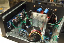
Here's my final chassis layout for a 63v/rail Honey Badger in a Deluxe 5U. I need to flip the boards so the caps are at the back, and mount the base with the flanged sides down. PSU's are stacked. I've got just barely enough room for some barrier blocks and grounds. I'm planning to make a vertical mounting panel for the toroids, which will also provide shielding. I have 14ga aluminum sheet I can use and bolt it directly to the chassis, behind the toroids. With the amp boards flipped I'll have just enough room to separate the toroids from each other with the same aluminum material (which also puts the amp board fuses near the back panel, and easier to access).
This chassis has proven very versatile and well built. I'm stuffing this about as full as you could; in fact there is no other layout possible. My only critique is the v3 PSU boards, had they been 1/2" less wide, would have fit perfectly. The amp input caps protrude just a bit too much for them to fit. But, this layout will work and give me shielding to boot.
This chassis has proven very versatile and well built. I'm stuffing this about as full as you could; in fact there is no other layout possible. My only critique is the v3 PSU boards, had they been 1/2" less wide, would have fit perfectly. The amp input caps protrude just a bit too much for them to fit. But, this layout will work and give me shielding to boot.
Attachments
Last edited:
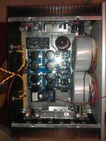
Here's my first build in a 4U deluxe case. It's a Leach clone on boards by Jens Rasmussen - the 10 output device type. PSU Boards are from chipamp.com - they will take 40 mm caps with 10 or 22.5 mm lead spacing. Caps are 10,000 uf in stacked supplies, 40,000 uf per rail counting the caps on the boards. The transformer is an Avel 600VA dual 40V. This Jens/Leach boards are a tight fit, but workable.
I originally thought I'd regulate the front ends, but this amp will likely end up powering my subwoofers, even though it sounds great. There is room to mount the regulators on the front panel. There's a Honey Badger coming this weekend...
I originally thought I'd regulate the front ends, but this amp will likely end up powering my subwoofers, even though it sounds great. There is room to mount the regulators on the front panel. There's a Honey Badger coming this weekend...
Attachments
Last edited:
Hi Andrew,
After reading your comments in another thread about fuse placement I was concerned that I might have a problem with the fuses. The rail capacitors are 10,000 uf, and after a hundred or so starts those 5A fuses haven't popped yet. I'll probably increase the value if the amp ends up in subwoofer duty with 4 ohm drivers.
No, my NTCs aren't bypassed. On my to do list. At the levels I listen there doesn't seem to be any significant rail modulation, though.
The input RCAs have about as small a loop as I could get with my big numb fingers. (spinal cord injury) The amp is dead silent, so I am not going to worry about it.
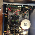
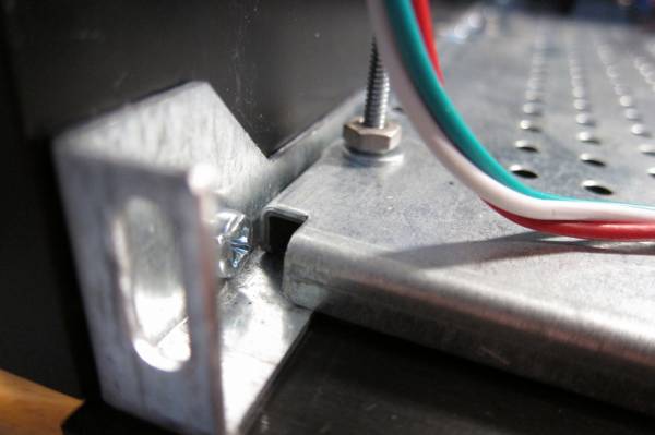
Starting to finalize my build with the 4U Deluxe and noticed that I cannot attach the faceplate with 4 screws. I can attach the top 2 screws (at their lowest setting) but the bottom two taps are still too high, i.e. not far enough into the slot on the heat sink bracket.
I have attached a picture to show the assembly. Is it correct?
Anyone else have this problem?
I have attached a picture to show the assembly. Is it correct?
Anyone else have this problem?
Attachments
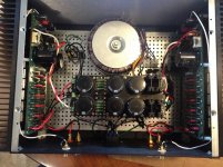
I also just noticed your base board is mounted wrong. The bottom rail must be mounted below the base board, not on top. If you keep it the way you have it now, you not going to be able to mount the bottom plate seamlessly. Unless it was your intention to have that gap at the bottom?
Last edited:
The joy of precision. If the heat sink brackets aren't at their closest possible position they front plate holes don't line up. That makes it line up perfectly when assembled, though.
You'll need to get longer bolts to attach the tray to the rails when you move it to the proper position. 1/2" long 6-32 flatheads will do and allow the nut to be fully engaged. Go to 5/8" if you want to use a washer. While at the hardware store, get something to attach the feet. I used a self tapping sheet metal screw, but others don't like that. You will probably need to drill the brackets out a bit to use 6-32 bolts.
If the heat sink brackets aren't at their closest possible position they front plate holes don't line up. That makes it line up perfectly when assembled, though. You'll need to get longer bolts to attach the tray to the rails when you move it to the proper position. 1/2" long 6-32 flatheads will do and allow the nut to be fully engaged. Go to 5/8" if you want to use a washer. While at the hardware store, get something to attach the feet. I used a self tapping sheet metal screw, but others don't like that. You will probably need to drill the brackets out a bit to use 6-32 bolts.
I had the same problem. When i finally got the 2 screws to the bottom left and right I had a hard time with the top left and right, so I loosened the screws to the heatink (top rail).
+1. Probably just need to loosen some other parts to "square things up" and get everything to properly align. I had that same experience. At first I wondered about the drilling precision, but after I modified my assembly technique it became clear that the case was superbly manufactured.
BK
I also did what Bobellis suggested - drill the existing hole so it can fit larger bolts so it fits through the feet and then into the heatsink bracket and then into the base board and then put a washer and nut on it. I used a round head for this, but you have to use a flat head for joining the base board to the heatsink bracket.
The joy of precision.
This worked for me. I just forced the HS brackets as close together as possible and the tap just makes it into position.
I think I will leave the incorrect tray mounting for the moment. I didn't bother with the plastic feet. Just stuck on some heavy duty rubber feet. OK for now.
Love the chassis. Going to listen now.
Thanks to all!
Member
Joined 2009
Paid Member
- Home
- The diyAudio Store
- Chassis Discussion