For the March 2018 build guide please go here: ACA (v1.1) Illustrated Build Guide
-----
Amp Camp Amp #1 – A Pictorial Build Guide
So you want to build an amplifier?
First read Nelson Pass’ article on Amp Camp Amp #1 if you haven’t already:
Amp Camp Amp #1
However, understanding this article is not necessary to build the amp. With the help of this guide, just about anyone should be able to build the Amp Camp Amp using only:
Ordering parts:
You can buy boards, kits, heat sinks, and power supplies right here on diyAudio: The diyAudio Store - Kits
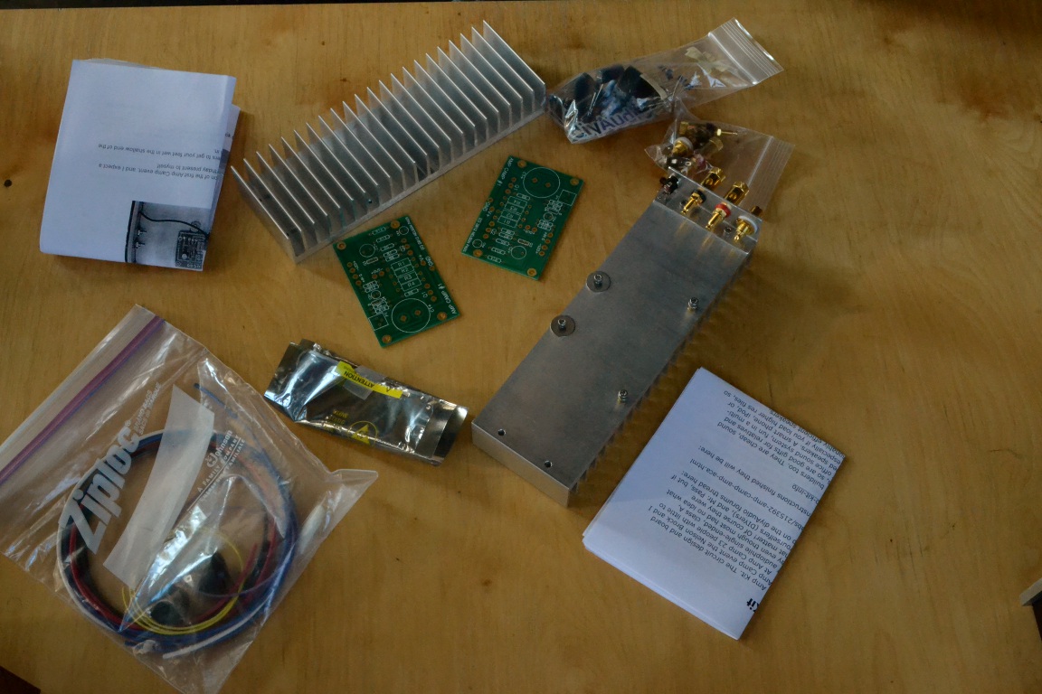 Take inventory of your parts
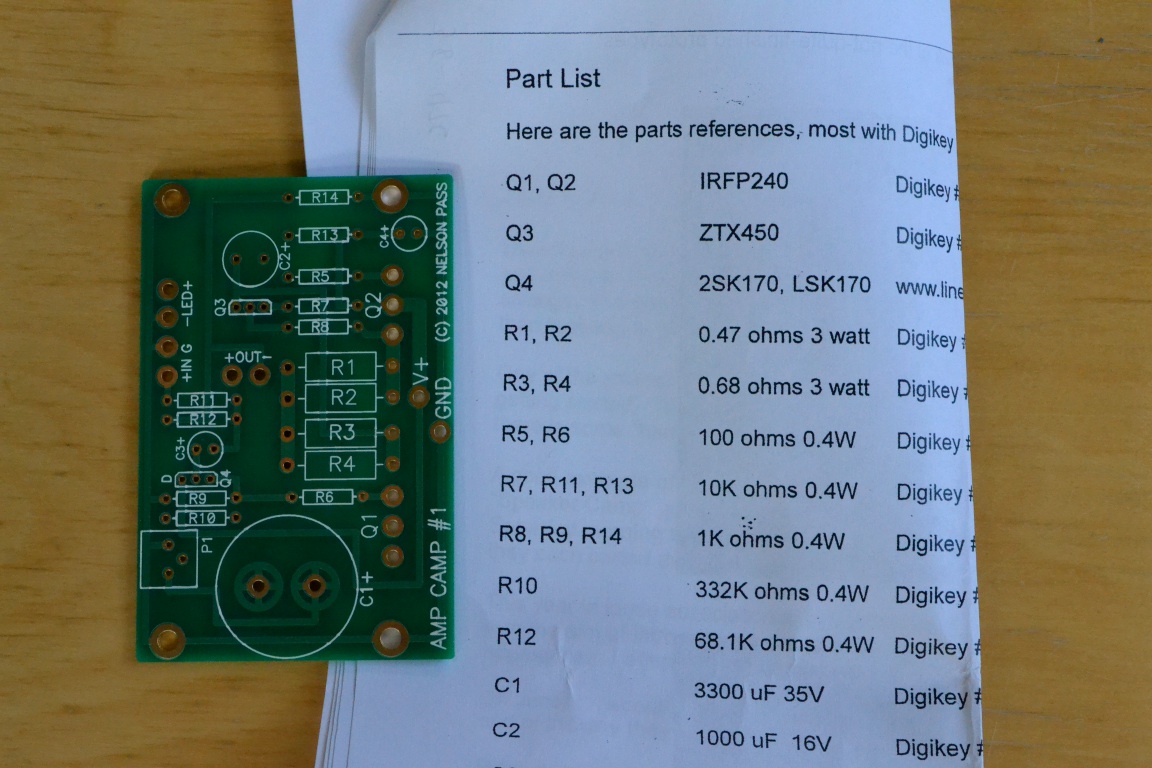 Keep your parts list in front of you as a reference to where parts go in the printed circuit board (PCB)
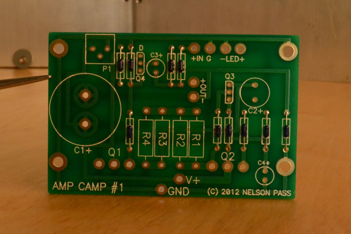
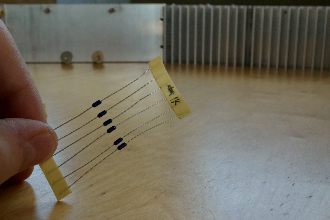 Attach the shortest components to the PCB first. We’ll start with the small resistors. The values are written on the sides of these resistors, but it may be easier to use a multimeter to check the values if the lettering is hard to read. It's best to do both.
 Bend the leads of each resistor downward so they are spaced to fit in the circuit board.
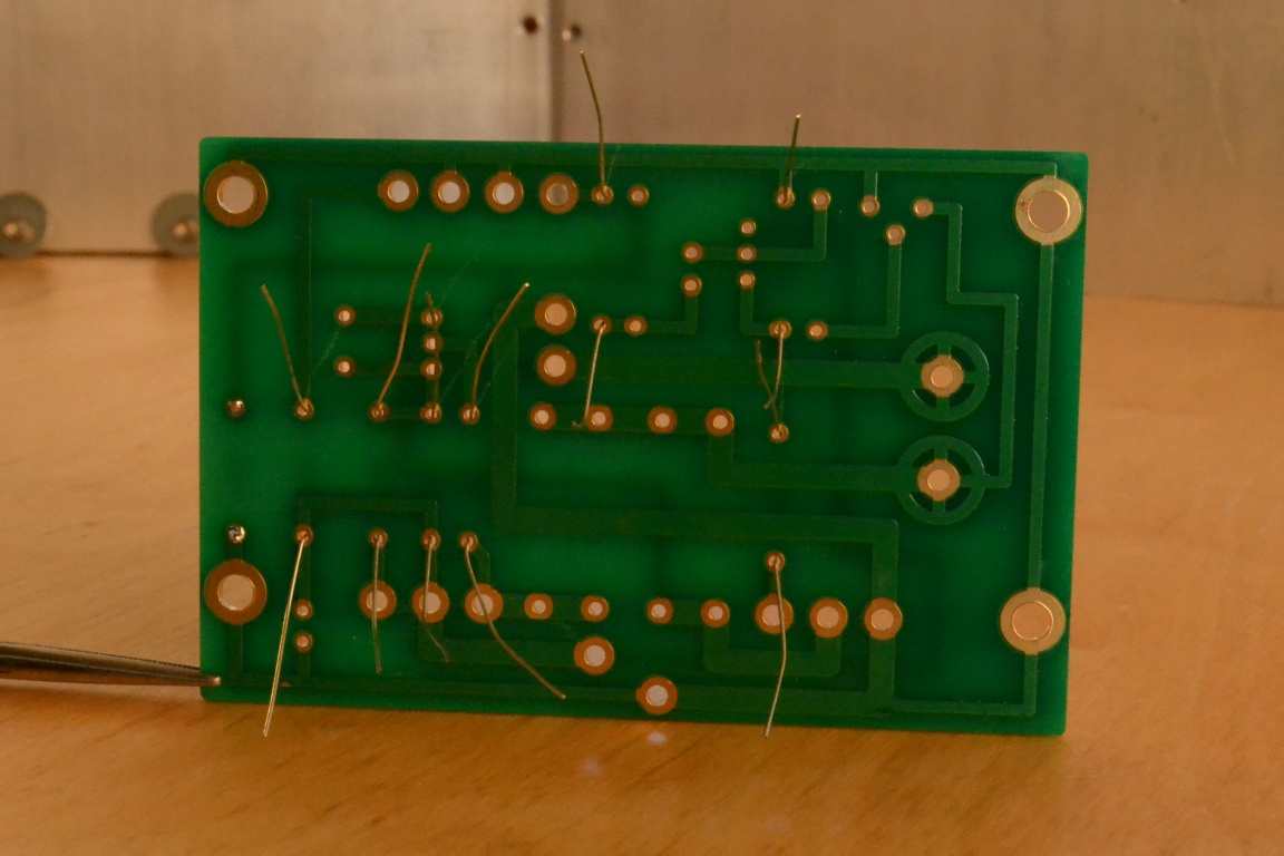
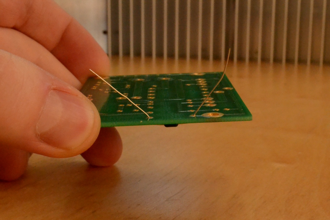 If you've never soldered it’s a good idea to learn about it and practice a bit first. There are many videos and descriptions of proper soldering technique on the web so I’ll not go into it here. Put the resistor though the proper holes and bend the leads on the back a bit so it stays in.
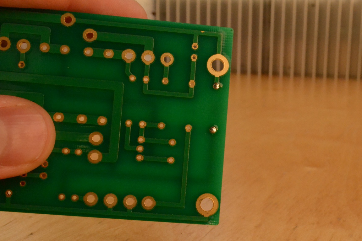 Flip the board over and solder in the resistor. Always cut the leads of all soldered components at the point just past where the blob of solder thickens near the board. If the leads are left too long they may short out against the heat sink.
 Repeat for R5-R14. You can place, solder, and cut multiple resistors at once to save time.
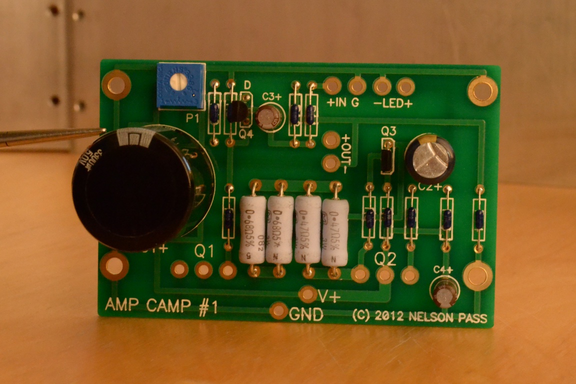
 Place R1-R4 and solder them. Note that R1 and R2 are .47 ohm; R3 and R4 are .68 ohm.
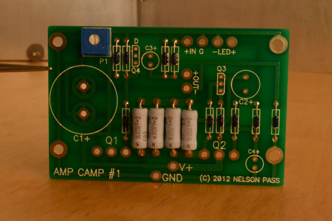 Place and solder in P1. This is a variable resistor we will use later to adjust the amp.
 Now we’ll install the capacitors. These parts are polar, meaning they have a positive lead and a negative lead. The capacitor can has a dashed white stripe down one side to indicate the negative lead. Often the positive lead will also be longer than the negative. Insert C2, C3, and C4 with the positive lead through the hole marked “+”, then solder from behind. Can type capacitors such as these should be pushed down snug against the board before soldering so they don't wiggle after being soldered. For now, leave C1 out, this will make installing the small signal transistors in the next step easier.
Q3 and Q4 will go in next. From afar both parts look quite similar.
Moving closer though shows that the shapes are somewhat different.
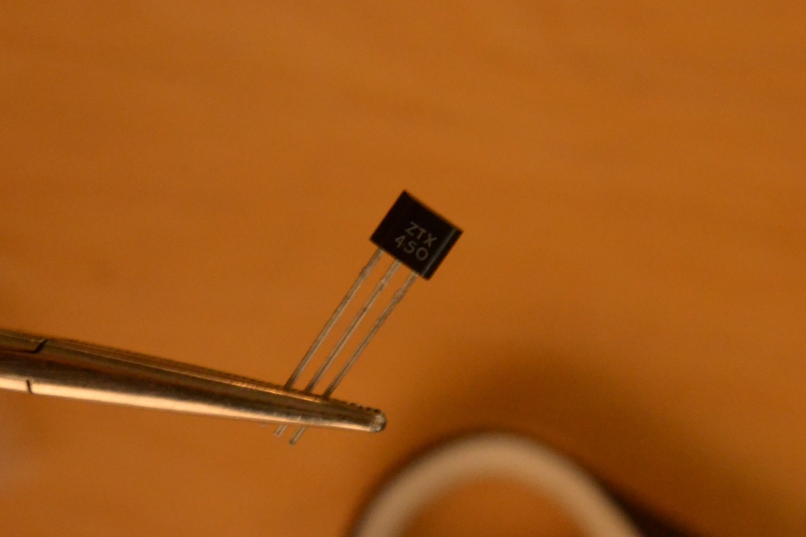 Each transistor is also marked with its part number. Q3 is ZTX450. Q4 is LSK170.
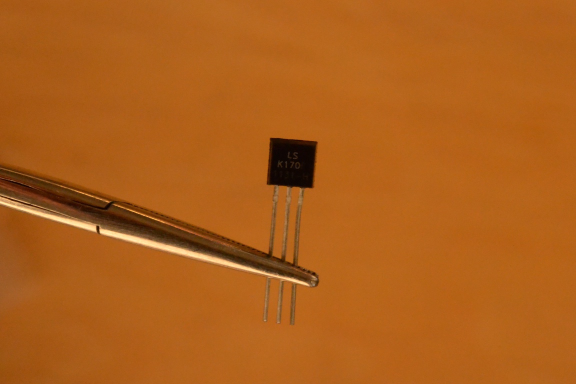 These photos have both been edited to make it easier to see the markings.
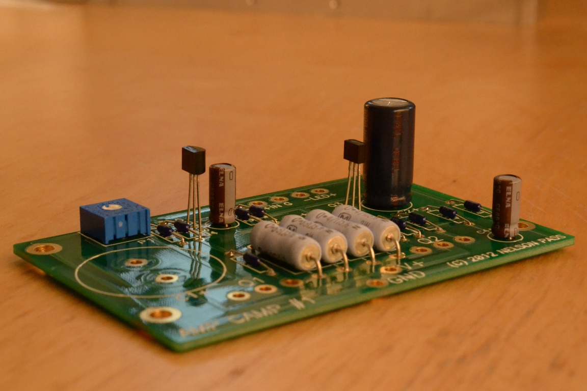 Put the transistors into the circuit board such that the flat side of its plastic case lines up with the flat side marked on the circuit board. Solder them from beneath. I like to put them far enough above the circuit board so I don’t have to cut their leads.
 Insert C1, pay attention to the polarity, and solder it from below.
 Now we mount the MOSFET power transistors, Q1 & Q2, to the heat sink. Get your mica insulators, grease, washers, and the longer M3 screws. Check to make sure the mica doesn't extend over the edge of the heat sink. I had to trim mine with a pair of scissors (carefully).
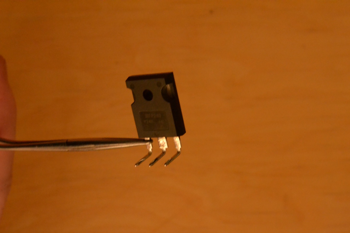 Bend the leads of each transistor upwards like so.
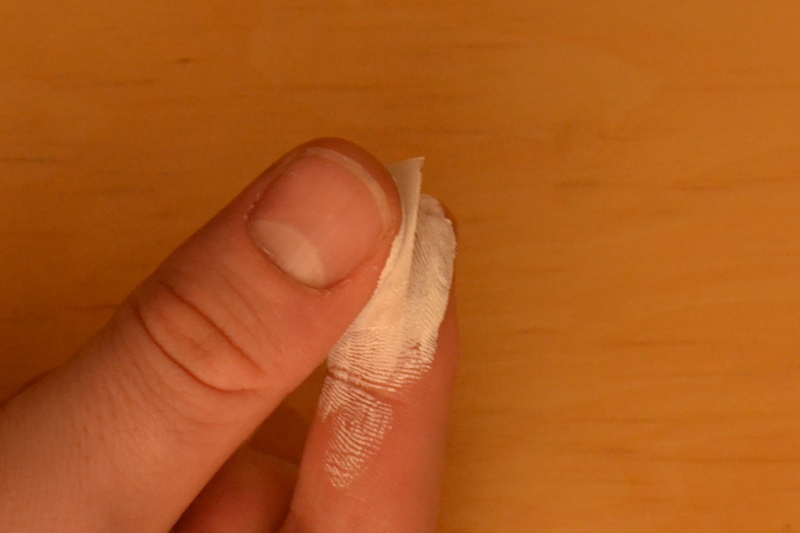 Open one of the packets with the heat sink grease or “white goop” and squeeze a bit out onto your finger. (Use about half the amount of how much toothpaste you use. One packet will easily do both the transistors.) Rub it between your thumb and forefinger. Spread the goop onto both sides of the mica, coating the entire thing with a thin layer.
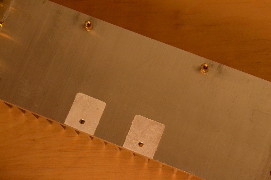 Line up the holes on the mica with the correct threaded hole in the heat sink and stick it down. The goop will hold it in place.
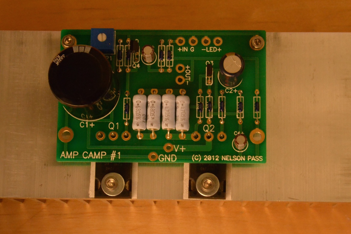
Screw the brass stand-offs at the top of the picture into the heat sink and tighten.
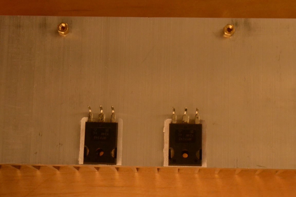 Place the transistors on the mica and screw down the bolts part way.
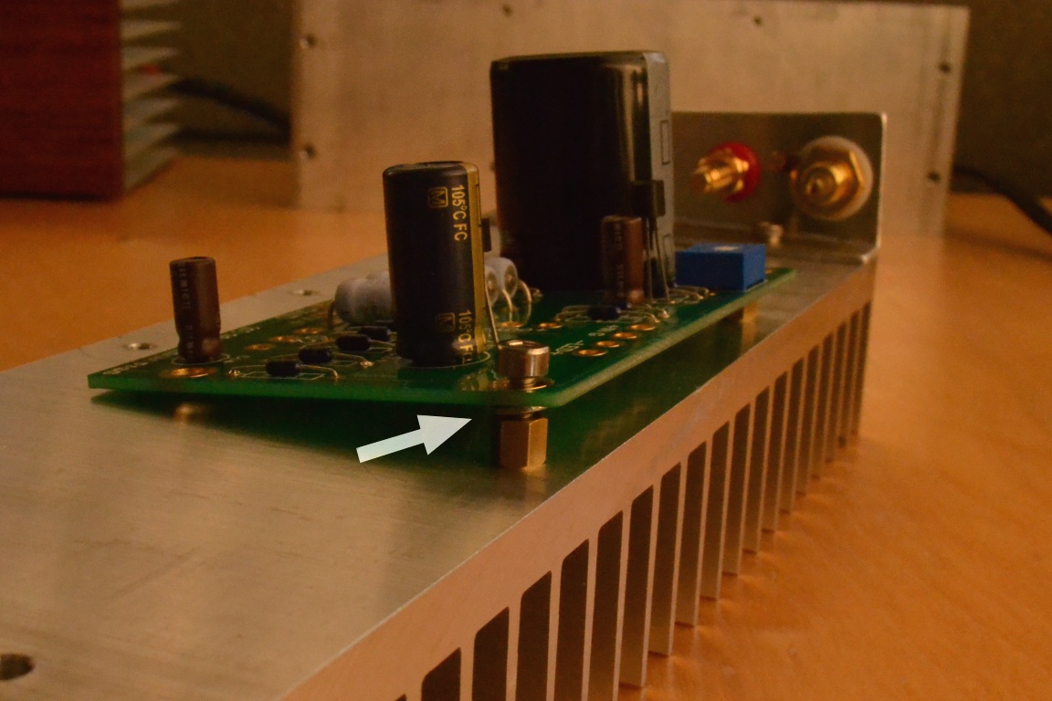 Before you tighten the transistor bolt, place the circuit board on top with the transistor leads going through the board. Tighten down the shorter M3 bolts through the circuit board into the stand-offs. You need to use the split washer between the board and standoffs (marked with an arrow) or the bolts won't tighten completely.
 Now put the long bolt through a washer and tighten it down through the transistor hole. Once everything is snug, solder the leads of the transistors to the board.
 Now begin to wire the connectors to the board. Strip some insulation from each end of the smaller (purple and yellow) wires, then twist them together.
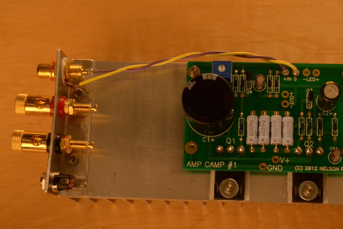 Solder the purple wire to the center pin of the RCA jack and the yellow wire to the tab sticking out. Run the twisted pair of wires to the point on the board marked IN and cut them to length. Remember that wire can always be cut shorter, but can’t be cut longer. Purple gets soldered to + and yellow gets soldered to G.
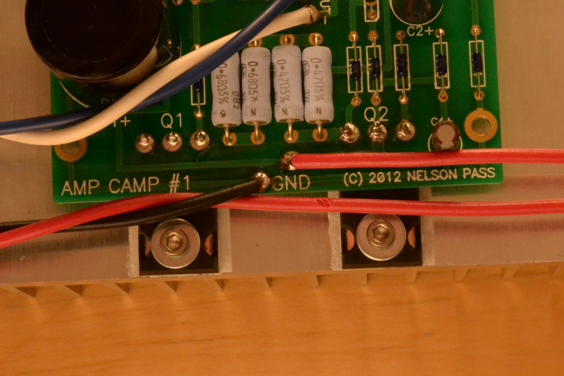
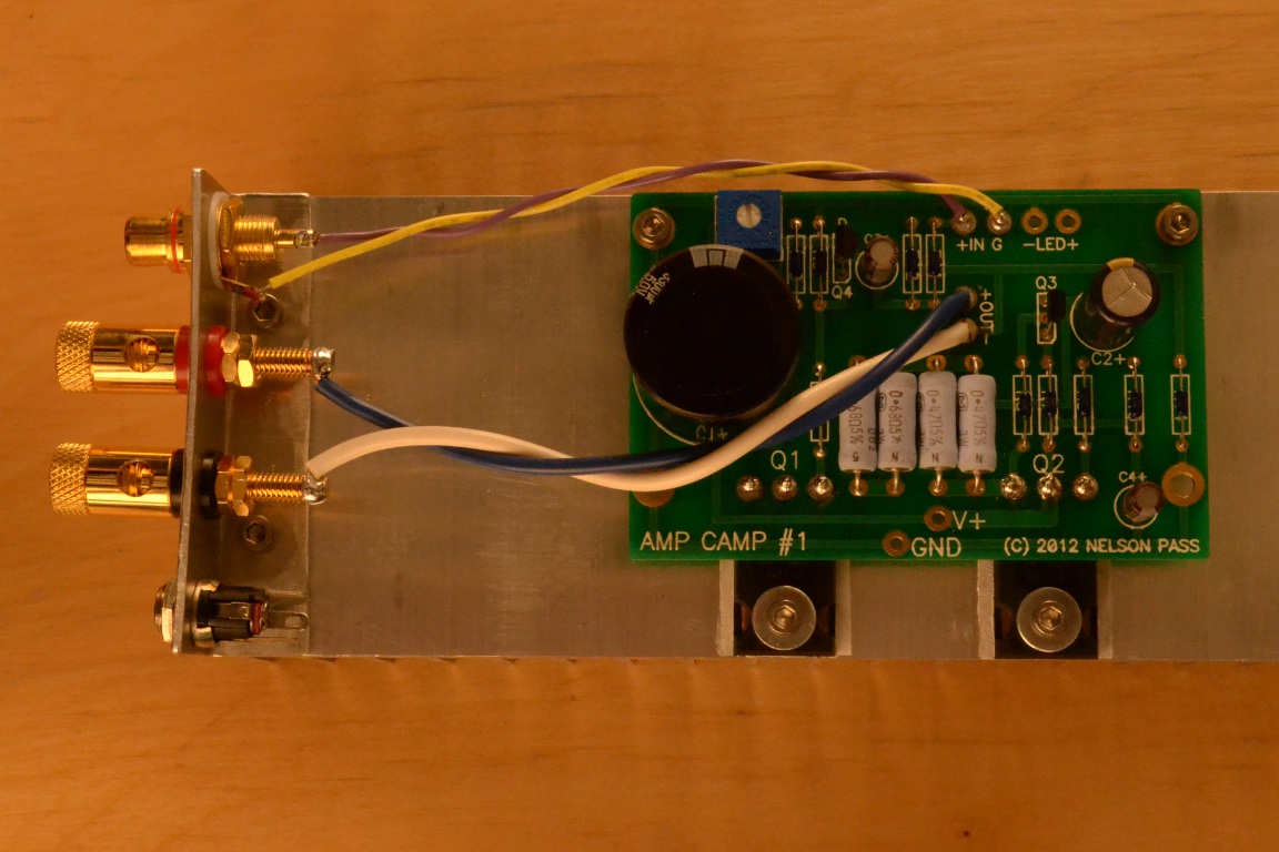 Strip about 1/2" of insulation from each end of two pairs of the larger wires. Solder each to one of the binding posts. Connect the red binding post to the ‘OUT +’ and the black post to ‘OUT –‘. After soldering, trim the excess wire. In the photos below I used blue and white wires. Don’t do that. Use the red wire instead of the blue. If you have your own wire at home, go ahead and use whatever colors you like, however, the amount of wire that the Amp Camp kit comes with means you need to save the blue wire for the switch (in a later step).
 Now we wire the LED. In this example just soldered it directly to the board. Some people will want to extend the LED to their front panel with some extra wire. Like the capacitors, the positive lead on the LED is longer than the negative one. There is also a small flat area on the edge of the LED on the negative side. Note that the LED is not required for the circuit and you may leave it out if you choose. You may also use a different color LED if you wish (the one provided is red).
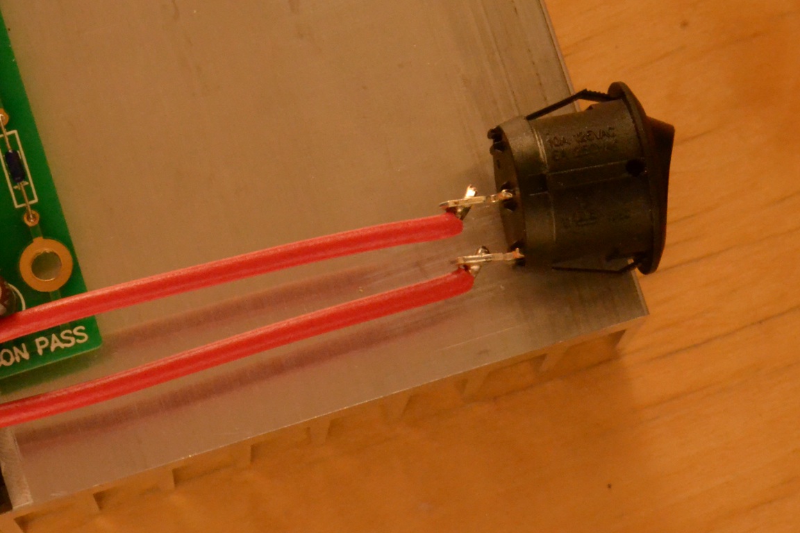
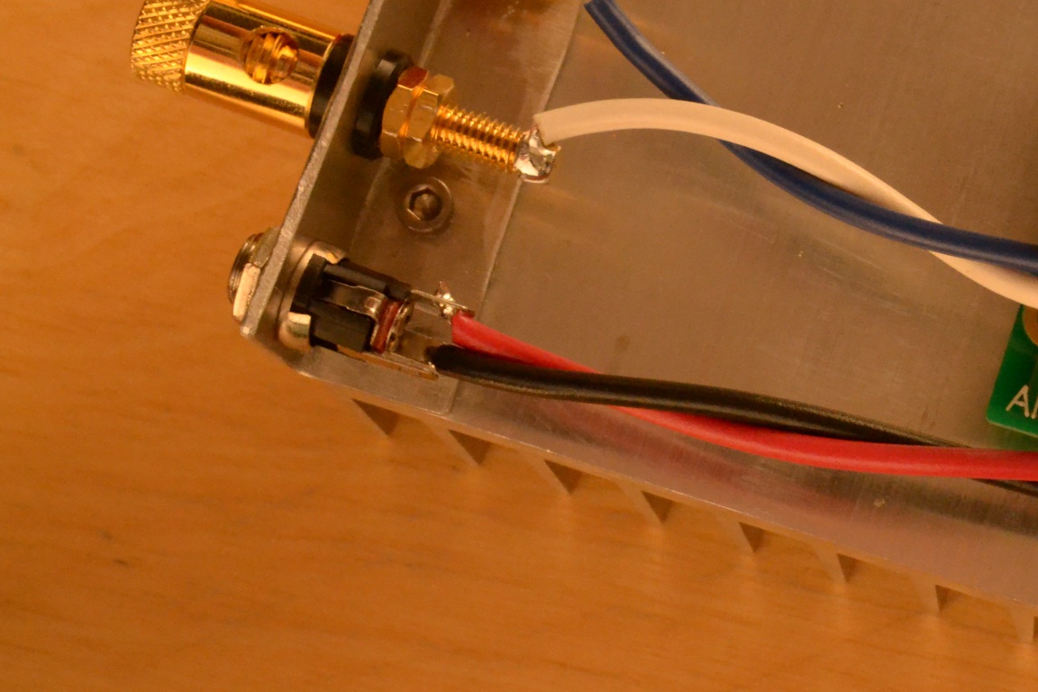
 The last thing to wire is the power and switch. Connect the blue wire to one terminal of your switch (in the pictures it’s red). Solder this to the point marked V+ on the board. Solder a second blue wire from the switch to the center pin of the power jack. Solder a black wire from the point marked GND to either of the remaining tabs on the power jack.
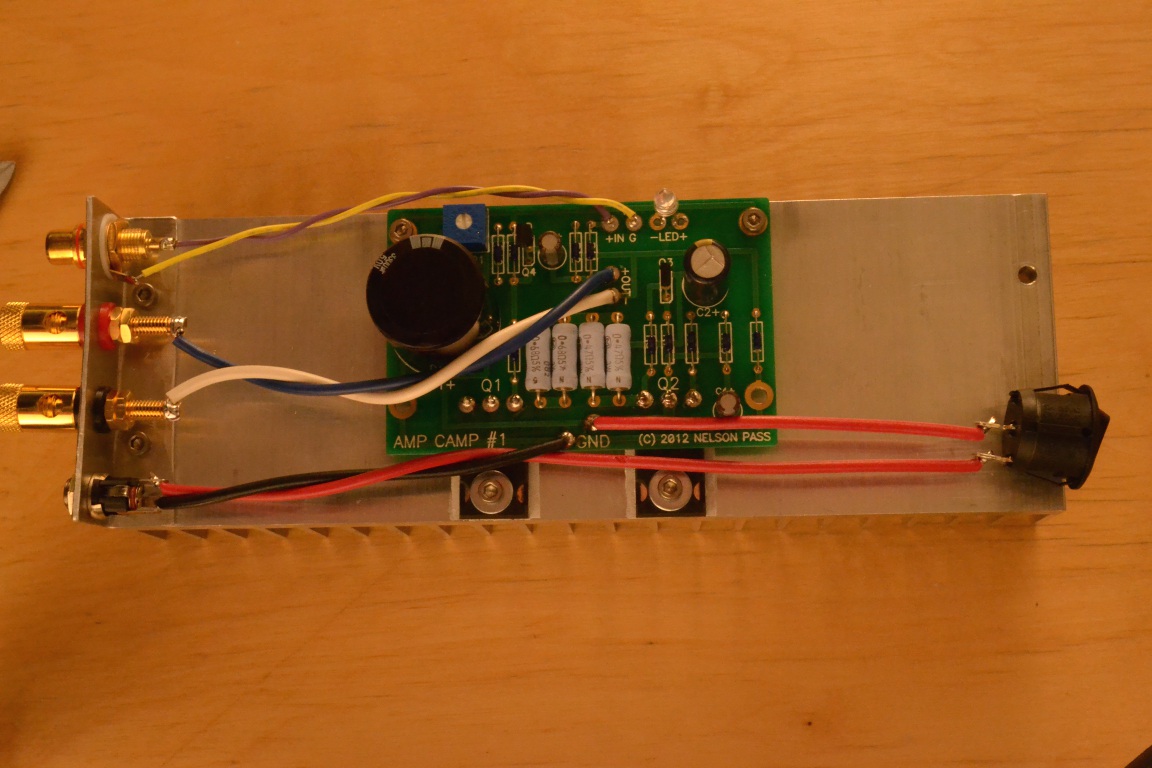
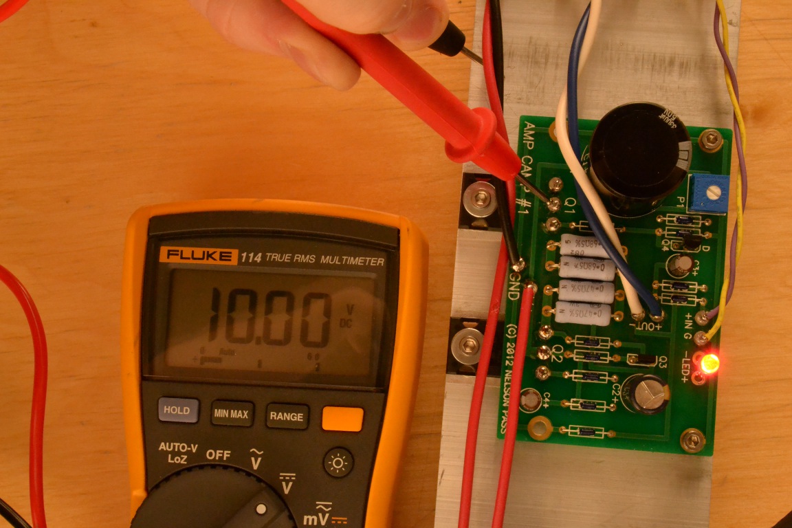 The entire amp is now complete. Although it technically works at this point, there is still an adjustment that needs to be done. Plug the power supply unit (PSU) into the jack, and the PSU power cord into an AC outlet, and turn on the amp to make sure the LED lights and there isn’t any smoke or burning parts. For this next step you will need a multimeter. Set the meter to DC voltage. Check the voltage between the center pin of Q1 and GND. It should be between 5 and 15 volts, but we want it to be 10. Using a small flat screwdriver turn P1 slowly until you get 10 volts. Clockwise raises the voltage, counter clockwise lowers the voltage. Leave the amp on for about half an hour. Re-measure the voltage on the center pin of Q1. It will have drifted away from 10v due to heat. Adjust P1 again until you get 10 volts. Your amp is now ready to roll. Note that the voltage does not need to be exactly 10v. Anything in the range 9.5v to 10.5v is acceptable.
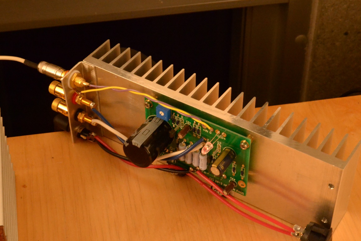 Now it’s time to hook up a source and speaker to your amp. Whenever you change the connections on an amplifier the power should be turned off. It may be a good idea to use a cheap test speaker the first time you hook up your amp. If something was done incorrectly it could break the speaker. Once you are satisfied everything is in good working order, it’s time to kick back, enjoy your handiwork, and contemplate your next audio project.
-Nelson-
-----
Amp Camp Amp #1 – A Pictorial Build Guide
So you want to build an amplifier?
First read Nelson Pass’ article on Amp Camp Amp #1 if you haven’t already:
Amp Camp Amp #1
However, understanding this article is not necessary to build the amp. With the help of this guide, just about anyone should be able to build the Amp Camp Amp using only:
- A soldering iron
- A multimeter
- A pair of pliers
- Wire cutters
- 2.5mm hex wrench
- Screw driver
Ordering parts:
You can buy boards, kits, heat sinks, and power supplies right here on diyAudio: The diyAudio Store - Kits
Q3 and Q4 will go in next. From afar both parts look quite similar.
Moving closer though shows that the shapes are somewhat different.
Screw the brass stand-offs at the top of the picture into the heat sink and tighten.
-Nelson-
Last edited by a moderator:
Do you know where I can buy a couple replacement resistors for the ones that came in my Amp Camp Kit V 1.6? I mistakenly soldered the wrong ones onto the board, clipped the leads and then realized they were wrong, desoldered them but am left with two with very short leads.
Is there an online source that supplies exact replacements in the US or what might you suggest? I don't need the entire batch f resisitors, caps and transistors that come with the kit as I only used a few so far.
thank you
Is there an online source that supplies exact replacements in the US or what might you suggest? I don't need the entire batch f resisitors, caps and transistors that come with the kit as I only used a few so far.
thank you
- Status
- This old topic is closed. If you want to reopen this topic, contact a moderator using the "Report Post" button.