Capacitor soldering problems...
What size iron are people using to solder the capacitors to the pcb? I have 25 watt iron with 2mm bit and it seems to be a bit of a problem actually melting enough solder on the pcb pads for the capacitors. Takes too long and I am afraid I may damage the capacitors if I leave the iron on too long. What is too long 5 secs 10 secs?
Any advice appreciated.
I don't think a 25 watt iron will damage the capacitors. However, I started using a temperature controlled iron decades ago. It just works better.
What size iron are people using to solder the capacitors to the pcb? I have 25 watt iron with 2mm bit and it seems to be a bit of a problem actually melting enough solder on the pcb pads for the capacitors. Takes too long and I am afraid I may damage the capacitors if I leave the iron on too long. What is too long 5 secs 10 secs?
Any advice appreciated.
The cap pads are big enough to make your life easier.
Heat only them until they pull the solder. Keep away from the cap' s wire, and only heat it directly when the solder has flown into the pad.
This should be a standard practice...
Small pads with narrow tracks will heat as quickly as leads on small through hole components. Here you can heat the pad and lead out simultaneously in about 2seconds.
Big pads with big tracks must be preheated with a well tinned iron until the solder melts on the pad. Only then should the iron be rolled, or slid, across the pad to touch the lead out to complete the joint.
Big pads with big tracks must be preheated with a well tinned iron until the solder melts on the pad. Only then should the iron be rolled, or slid, across the pad to touch the lead out to complete the joint.
Small capacitors
I'm building a F5 using the diyAudio Universal Power Supply Boards.
I have a question about two capacitors in the circuit:
1) In the Nelson Pass power supply circuit he uses a .0033uf cap in parallel across the mains. I've been doing some reading and I believe this is for emi/rfi suppressing. The question is what type (material) and ratings does this cap need to be?
2) On the power supply board C17 and C18, part of the snubber circuit. BOM says .1uf 63-100v. Again what type (material) would be best?
Thanks,
Kevin
A big improvement of the BOM would be to have a more detailed specification of each part and also article numbers from some of the big distributors like Mouser, Farnell etc.
The 3.3 nF cap should be a cap approved for X-type applications, normally polyester.
C17-C18 , polyester is fine.
The 3.3 nF cap should be a cap approved for X-type applications, normally polyester.
C17-C18 , polyester is fine.
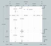
We'll publish a full physical diagram shortly.
The cap board has four holes in the middle in an 80x80 square, which allows it to be attached to the back of the new Deluxe chassis front panels as a single or dual PSU, or on the perforated base, or on risers either attached to the base, or perpendicular to the front, or flush with the front, mounted up or sideways or... hard to explain but we'll have diagrams galore when I get a moment to make them.
All other holes on the cap and diode section are on the new 10x10 grid pattern, so again you can attach them to the base, front or risers and spun around in any orientation.
Full mounting specs coming soon...
I pre ordered several Universal Power Supply Boards and am trying to collect and order my parts. I was planning on using TO247 diodes with heatsinks. The board has an outline of a heastsink. Is there a part number or designation for a heatsink that fits the board.
Thanks.
dante
Thanks.
dante
Beginner Question
This may seem a simple question to those in the know but I am trying to figure out how to connect the transformer to the diode boards.
I have a 49v-0-49v transformer (one for each channel), so three wires coming out of the secondary two red one yellow. How do I connect these to the diode board, AC1A, AC1B and AC2A, AC2B?
Simple answer please.
Wire 0 = your ground
The other ones shall go to AC1A and AC1B. You can't use two rectifier bridge with a center tap transformer. You must have two separate secondary windings if you want to have two rectifier bridges.
oh! looks like I need to get new transformers!
I pre ordered several Universal Power Supply Boards and am trying to collect and order my parts. I was planning on using TO247 diodes with heatsinks. The board has an outline of a heastsink. Is there a part number or designation for a heatsink that fits the board.
Thanks.
dante
Check the UMS - http://www.diyaudio.com/forums/imag...sal/universal-mounting-specification-v2.1.pdf
The only pre-drilled pre-tapped heatsinks we sell are the ones in the Deluxe Chassis:
Full width with 40mm Heatsinks - Chassis
- Status
- This old topic is closed. If you want to reopen this topic, contact a moderator using the "Report Post" button.
- Home
- The diyAudio Store
- Universal PSU, Capacitor and Diode Combination Board (V2)