Isn't 1-3 ohm a more correct value if you want to remove the parallel resonance?
Snubber guide lines
Snubber guide lines
I have only 10000 uf caps at 30 mm, can I place four larger caps under the board upside down . is there room to solder them in place as a way to increasing capitance?
I was thinking to do the same thing but the body of the caps is really close to the soldering pads. It might be dangerous for the caps, especially since we need to keep the iron there enough time to heat the pads.
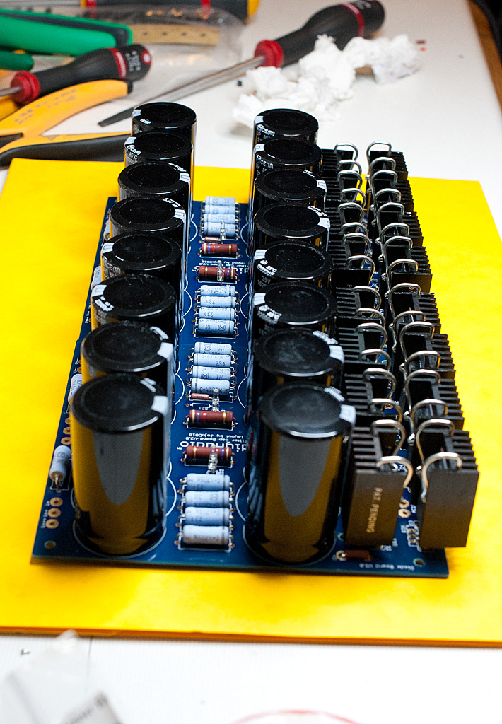
I built a couple of boards for my F5 a few months back.
I have no big problem, except that they were not really designed to be used with heatsinks (as it was suggested as an option).
The holes for the secondaries and the jumpers are very close to the diode holes, so if you attach heatsinks it is really a PITA to fit the cables in there. And in some cases (like the jumper holes) the heatsinks sit right on top of them, creating mechanical problems and possible shorting issues
It is now clear that space for heatsinks to-220 diodes packages must be considered. Thank you for the feedback, we will consider your inputs in the next revision.
Using screw terminal caps off the board
I have the opportunity to get some 22000uf Kendeils at a discount but they are with screw terminals K61 TYPE. These will obviously not fit on the board, so does it matter if I just have leads running from the board to the capacitors mounted on the side of the enclosure? Anything to worry about?
I have the opportunity to get some 22000uf Kendeils at a discount but they are with screw terminals K61 TYPE. These will obviously not fit on the board, so does it matter if I just have leads running from the board to the capacitors mounted on the side of the enclosure? Anything to worry about?
I have the opportunity to get some 22000uf Kendeils at a discount but they are with screw terminals K61 TYPE. These will obviously not fit on the board, so does it matter if I just have leads running from the board to the capacitors mounted on the side of the enclosure? Anything to worry about?
Then why use the boards??
I agree there is no reason to use the entire boards if you plan to wire the caps somewhere else. You will just lose chassis real estate and run unnecessary lengths of wire.
Just snap and use only the rectifier parts. The resistors can easily be soldered or screwed straight on the caps
Just snap and use only the rectifier parts. The resistors can easily be soldered or screwed straight on the caps
")

We're just putting the finishing touches on a very slick and much improved and enhanced PSU board - you will be glad you waited as it has many new features and options. It should be in the store within 45 days.
Day 52 - PSU WRU?
- Status
- This old topic is closed. If you want to reopen this topic, contact a moderator using the "Report Post" button.
- Home
- The diyAudio Store
- Universal PSU, Capacitor and Diode Combination Board (V2)