
I just got a PS board.
A couple things to consider for the next batch.
I have a bunch of 35mm caps and can't fit 8 on the board. Only needed the spacing to be a little farther apart.
The pads for the power resistors seems a bit small. Will have to scrape some of the solder mask off so the joint doesn't fail from the heat.
I just got a PS board.
A couple things to consider for the next batch.
I have a bunch of 35mm caps and can't fit 8 on the board. Only needed the spacing to be a little farther apart.
The pads for the power resistors seems a bit small. Will have to scrape some of the solder mask off so the joint doesn't fail from the heat.
Hi,
I will keep that in mind in the event of future revisions.
Thanks for your feedback!
Does anybody know the pitch of the output terminals on the board?
The V+ and V- pads are 5.5mm apart while the Ground pads are 6mm apart.
The V+ and V- pads are 5.5mm apart while the Ground pads are 6mm apart.
So everything needs to be redrilled if you want to fit terminal blocks? Because I don't see any 5.5mm or 6mm blocks out there.
So everything needs to be redrilled if you want to fit terminal blocks? Because I don't see any 5.5mm or 6mm blocks out there.
It was not meant for any terminal blocks in the first place. Of course we are always open to make future revisions more user friendly and those ideas are being seriously considered.
Last edited by a moderator:
Hi Andrew,
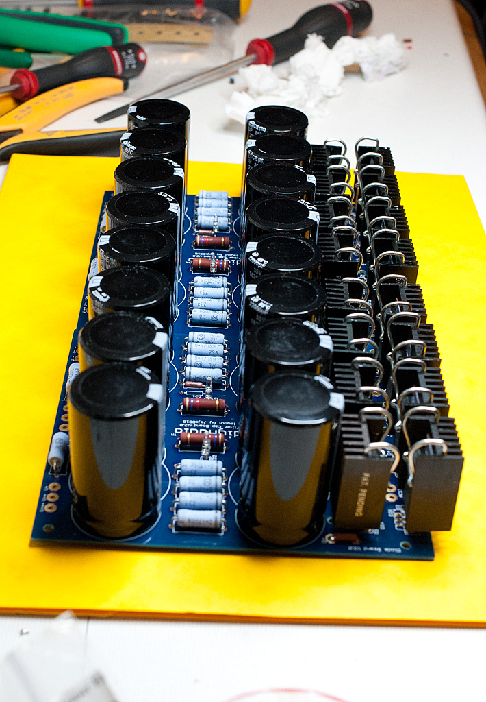
I bought this set of boards. They definitely were not well thought out. You can't fit 8 35mm snap-ins on the board and I have lots of them. Don't ask me why there's an extra set of holes in the center. The solder pads for the resistors are too small. Not enough surface to prevent thermal failure.
The diode boards have skimpy narrow traces. Wouldn't have cost anymore to make them wider. Can't fit the transformer leads into the holes. Solder pads are too small also.
I don't know who designed them but they definitely need more experience.
LabJR - The BOM states that these boards are compatible with 8x30mm caps or 4x35mm caps. This was a deliberate design decision made at the time to allow for other optimizations in the design. Thank you for alerting us to the fact that while the BOM has always stated this, the actual sales page doesn't actually say anything about what caps are compatible and what are not. To make it easier to see (in case people don't read the BOM before purchasing), I have updated the description in the sales page and I have refunded your purchase as obviously this was not the correct board for you and I apologize if you were mistaken in thinking that it could handle 8 x 35mm caps.
Actually, all our sales pages could use some polish and we will be updating them right after we finish updating all our BOMs with Digikey part numbers (which is our current mission (no pun intended)) which is our current mission to make life easier for customers.
To answer your questions:
These boards are tried, tested and proven in the field to be well manufactured, affordable and feature a wide range of component and mounting options. There is always room for improvements and we welcome constructive criticism, feedback and ideas. As time goes on we will iteratively improve the design, but please keep in mind that this design works perfectly well, and it is currently successfully powering hundreds of amplifiers across the planet as we speak.
AndrewT has made some excellent suggestions for modular compatibility and we will definitely be considering them for the next revision.
This is the first iteration of this product and thanks to the great feedback from you guys we have a lot of ideas for how to improve it in the future. Thanks to everyone who has asked questions and proposed alterations for their constructive feedback to this board.
Actually, all our sales pages could use some polish and we will be updating them right after we finish updating all our BOMs with Digikey part numbers (which is our current mission (no pun intended)) which is our current mission to make life easier for customers.
To answer your questions:
- The extra holes make it easy and convenient to cut/snap off and mount the board to a heatsink or the perforated base featured in our chassis.
- The diode boards traces are sufficient for 15 Amps. I will add this to our product specification information.
- The transformer lead holes accept 1.6mm leads, and I will add this to our product specification information. Thanks for the feedback that your trafo leads are larger in diameter than this - we will definitely consider increasing the hole size in future revisions.
- We do appreciate your feedback on the pads and will consider making them larger in the next revision if possible. This is the first we've heard of this being an issue but we do want to make this board as easy to populate and solder as possible for every possible combination of parts and equipment.
These boards are tried, tested and proven in the field to be well manufactured, affordable and feature a wide range of component and mounting options. There is always room for improvements and we welcome constructive criticism, feedback and ideas. As time goes on we will iteratively improve the design, but please keep in mind that this design works perfectly well, and it is currently successfully powering hundreds of amplifiers across the planet as we speak.
AndrewT has made some excellent suggestions for modular compatibility and we will definitely be considering them for the next revision.
This is the first iteration of this product and thanks to the great feedback from you guys we have a lot of ideas for how to improve it in the future. Thanks to everyone who has asked questions and proposed alterations for their constructive feedback to this board.
Last edited:
I built a couple of boards for my F5 a few months back.
I have no big problem, except that they were not really designed to be used with heatsinks (as it was suggested as an option).
The holes for the secondaries and the jumpers are very close to the diode holes, so if you attach heatsinks it is really a PITA to fit the cables in there. And in some cases (like the jumper holes) the heatsinks sit right on top of them, creating mechanical problems and possible shorting issues
I built a couple of boards for my F5 a few months back.
I have no big problem, except that they were not really designed to be used with heatsinks (as it was suggested as an option).
The holes for the secondaries and the jumpers are very close to the diode holes, so if you attach heatsinks it is really a PITA to fit the cables in there. And in some cases (like the jumper holes) the heatsinks sit right on top of them, creating mechanical problems and possible shorting issues
Thanks for the feedback Dimkasta. We are going to review the spacing for the heatsinks in the next revision.
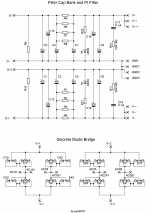
JoJo, your schematic shows 1r for R11 and R12, and your BOM shows 10r 3w. Which would be correct or does it matter for the snubber. thanks, John
It should read 10R. Please do follow the BOM. Thanks
Attachments
- Status
- This old topic is closed. If you want to reopen this topic, contact a moderator using the "Report Post" button.
- Home
- The diyAudio Store
- Universal PSU, Capacitor and Diode Combination Board (V2)