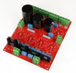
This thread is for discussions about the Universal PSU, Capacitor and Diode Combination Board. For more information on this product, please see the product page below.
Threads on diyAudio that relate to this product (If we have missed one, please post it in this thread and we will add it to the list):
Threads on diyAudio that relate to this product (If we have missed one, please post it in this thread and we will add it to the list):
- No threads yet - yours could be the first!
Last edited by a moderator:
R11 + R12
Hi, On the schematic R11 + R12 are 1ohm resistors but on bill of material they are 10ohm. Which is correct, if it changed from 1 to 10ohm what was the reason? The snubber with 1ohm cuts at 1.5Mhz and with 10ohm at 150Mhz> Does it make a difference? I would have thought the lower (1ohm) is better?
Thanks
I think you would have a more "Universal" product if you kept the ground busses separate for each polarity, instead of common, with a means for jumpering them together at the output end, if desired. Not much point in using two separate bridges unless the returns for each polarity are kept separate until after the power supply output, or with an option to stay separated until a central ground on the amplifier board.
Hi, On the schematic R11 + R12 are 1ohm resistors but on bill of material they are 10ohm. Which is correct, if it changed from 1 to 10ohm what was the reason? The snubber with 1ohm cuts at 1.5Mhz and with 10ohm at 150Mhz> Does it make a difference? I would have thought the lower (1ohm) is better?
Thanks
Hi,
Sorry for the confusion but it was actually meant to be 1 to 10 ohms and with the same capacitor, it would be up to the builder where he/she would like to set the snubber frequency.
Thanks
I think you would have a more "Universal" product if you kept the ground busses separate for each polarity, instead of common, with a means for jumpering them together at the output end, if desired. Not much point in using two separate bridges unless the returns for each polarity are kept separate until after the power supply output, or with an option to stay separated until a central ground on the amplifier board.
Hi,
I will keep that in mind in the event of future revisions.
Thanks for your feedback!
Jan Dupont and I made a similar and bigger board a few years ago for Jan's Lynx amp.
http://www.diyaudio.com/forums/group-buys/116218-lynx-power-amp-pcb-group-buy-interest.html
http://www.diyaudio.com/forums/grou...mp-psu-board-e-g-lynx-amp-10.html#post1693370
http://www.diyaudio.com/forums/group-buys/116218-lynx-power-amp-pcb-group-buy-interest.html
http://www.diyaudio.com/forums/grou...mp-psu-board-e-g-lynx-amp-10.html#post1693370
Attachments
Last edited:
I think you would have a more "Universal" product if you kept the ground busses separate for each polarity, instead of common, with a means for jumpering them together at the output end, if desired. Not much point in using two separate bridges unless the returns for each polarity are kept separate until after the power supply output, or with an option to stay separated until a central ground on the amplifier board.
A very good point (excuse the pun) you are making. Single STAR GROUND POINT.
Cap question ?
Hello every-one, When using the psu board for constructing a "F4" amp, is it ok to use 35 to 50v caps when the transformer has dual 18v secondaries ? The manual says to use 25v... Could someone please explain why a higher voltage rating could cause a problem ? Thank-you
Hello every-one, When using the psu board for constructing a "F4" amp, is it ok to use 35 to 50v caps when the transformer has dual 18v secondaries ? The manual says to use 25v... Could someone please explain why a higher voltage rating could cause a problem ? Thank-you
Caps?
Could folks give a list of the brand and part # of PSU caps they are using and why they choose them?
I am not familiar with the "speed" rating of caps, just voltage, farads, and ESR.
Looking at some Panasonic Electrolitics because of the value, but wonder if spending 5x on something more esoteric will change the sound drastically.
Mouser gives 4 different part numbers for the same cap, and the prices change a bit, but the data sheet does not show what the differences are.
Thanks.
More capacitor questions ?
Will the pcb handle using 4 x 33000uf caps as opposed to 8 x 15000uf ? The F4 manual shows a 120,000uf of total capacitance. If so what changes such as resistor values... need to be done ? The transformer I have is a 400VA - 2 x 18v secondary ! Any help would be greatly appreciated. Again thank-you everyone !
Will the pcb handle using 4 x 33000uf caps as opposed to 8 x 15000uf ? The F4 manual shows a 120,000uf of total capacitance. If so what changes such as resistor values... need to be done ? The transformer I have is a 400VA - 2 x 18v secondary ! Any help would be greatly appreciated. Again thank-you everyone !
Is ok to mount capacitors up-side down ? After looking over the psu board I had thought to possibly use 12 x 10,000uf caps. Mount 8 on top than 4 up-side down on the bottom in the larger cap slots.... This gives me the 120.000uf needed and the additional cost and labor would be less needing 4 more caps and a set of stand-offs.
I don't see any reason why it shouldn't work. I have not read any literature stating it's bad to mound caps upside down, unless someone can point me to one as I have less and less time to read nowadays.
Just be mindful of the pin orientation/polarity when installing those capacitors.
Just be mindful of the pin orientation/polarity when installing those capacitors.
That is sounds like good news ! What do you and/or anyone else think of these caps ? LKG1V103MESBBK Nichicon | Mouser
Last edited:
Those caps looks great. I have used 25V caps with 18V secondary toroidal transformer (as recommended by Nelson Pass in his manuals) without any problems since the power supply is supplying a Class A amp that draws current constantly. That way, you may try to look for 25V 15,000uf caps with a diameter of 30mm and LS of 10mm.
If you plan on doing the "top and bottom" installation, you can use 30mm sized caps on top and then 35mm caps at the bottom side. Just an idea I thought you may like.
don't be afraid to go a little bit over the specified 120,000uf...
"It's better to have more capacitance and not need it, than need capacitance and not have it..."
The reason for wanting to use the above posted Nichicons is I have a dozen of them from another unfinished project. The PASS manual says to use 25v, what is the worst thing that could happen if using 35v ? I have looked at a lot of other caps but the problem is either there not stocked or many have to great of a min order.
- Status
- This old topic is closed. If you want to reopen this topic, contact a moderator using the "Report Post" button.
- Home
- The diyAudio Store
- Universal PSU, Capacitor and Diode Combination Board (V2)