Hi Salas, I am not able to understand this part...where are we using the 3W resistors?
Those are the fat constant current setting resistors located nearer to the power input side of the board.
Those are the fat constant current setting resistors located nearer to the power input side of the board.
Ok I need help, can you guide me on the schematic...can’t seem to see them on BOM list too
In the BOM and on the silkscreen there are two 68R per side making 34R current setting resistors because arranged in parallel. But people who want to "hot-rod" the Mezmerize for larger standing current in its shunt regulators put single lower value higher power resistors in their place. Around 10R each. For reasons of even better sound quality but the dissipation on the sinks and on those resistors gets higher of course.
Got it, that's why 3W resistors...make sense. I see few posts where the LED's stop glowing after some time...probably more current than required through them...what if we solder a 1/8W current limiting resistor (restricting upto 2 - 3 mA) to each LED, this could ensure they glow all the time, keeping 1.8V consumption intact. Sorry, haven't calculated impact to the overall circuit
Those are usually problematic generic quality LED samples or have had long time under the soldering iron. They are supposed to be 20mA nominal LEDS to be run at half their rating. In general the Mez is a reliable DCB1, don't modify it, don't use more than 10mA IDSS. No resistor is going to restrict the current because its coming from a constant current source, the rail voltage will go high instead. To have less current in the LEDS the way is to use low IDSS for those JFETS that are in series to each string of them towards ground.
So if we control JFET Idss, then that's the current that should ideally get distributed in the LED's ...okTo have less current in the LEDS the way is to use low IDSS for those JFETS that are in series to each string of them towards ground.
Hi. I just finished building and wanted to just double check that my initial test results are ok and ask a couple of additional questions, just to put my mind at rest.
I've a 20 ohm resistor in for testing, but I'm going to add a second each side in parallel to bring it down to 10 when I'm happy that it's happy. Test results are:
Across R1
Neg supply: 1.94V
Pos supply: 2.19V
Power
+Vout: 10.66V
-Vout: 10.06V
Output DC Offset
R: -2 mV
L: +2.2mV
1. That all look OK?
2. Negative DC offset on the right channel is not a problem or indicative of my putting the jFETs the wrong way around?
3. It's only been on for 5 or 10 minutes but I'm seeing about 0.2mV variation on the DC offset. Is that a concern?
4. I went with a 120VA +/-15V transformer (am planning to hang a few more modules off it) and it's giving +/- 17.6V AC resulting in +/- 22.8V at the smoothing caps. Does that sound like too much?
5. Any reason I can't power a lightspeed from the relay regulator circuit? I'm not using the source switching so just the one (5V) relay on there.
6. the LEDs are all lighting up at a reasonable intensity, but the positive set are noticeably (but not worryingly) brighter. I assume that's just the difference in the supplies and to be expected?
Last edited:
1. Yes
2. No, negative is bit better actually, indicating best positioning between two slightly different JFETs in a pair. But it does not change anything significant in practical performance either since we are facing minimal offset values here.
3. Normal, its about thermals
4. More voltage is even good for the CCS MOSFET parasitic capacitance performance when the sink can handle the extra heat that extra voltage produces
5. There is much voltage drop across the reg chip from your raw DC down to 5V and the only reason to can't power anything extra would be the heat penalty. On the other hand if there is some well working clip on heat sink on it that does not suffer too high heat when powering a lightspeed also why not. You check the situation and decide.
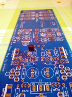
6. That's normal. The Mez is rigged to do that. Plays better now that it runs low CCS mA with that planned asymmetry. When you will go higher mA with lower Ohm setting resistors its no longer necessary, and you can perform this "leg trick" to restore equal LED currents. Lift the middle leg of that JFET only, bend and solder it to next leg on its right, as in the attached picture. Actually since almost everybody uses higher than lukewarm CCS setting I will be undoing that inherent asymmetry in LED currents on next opportunity of a newer diyA boards batch.6. the LEDs are all lighting up at a reasonable intensity, but the positive set are noticeably (but not worryingly) brighter. I assume that's just the difference in the supplies and to be expected?
Attachments
I've been continuing to tweak my build. I'm a little embarrassed to post pics as the wiring isn't all tidied up yet and I've had to shoehorn it into a grubby salvaged chassis until I can stretch to a new one and all the associated metal working kit. It will come though.
I did the leg trick, but I'm concerned I've damaged the transistor. Everything tests just fine except I'm now seeing 1.75V across the negative shunt resistor and 2V on the positive. That ok or should I replace the transistor? I've read many millions of posts on the Mez and related boards but I never did find the leg trick info, just references to it, so I'm flying a little blind.
It sounds great by the way. I'll expand on that asap.
")
Its due to different VGS between NMOS & PMOS. Higher VGS leaves less voltage across the setting resistor when subtracted from the three LEDS Vf total. You can use a lower Ohm setting resistor or combination in the lower achieving side. Like 8.2R vs 10R on the higher side. But 25mA difference does not change the transconductance of those big MOSFETS any significantly. More a matter of matching measurements aesthetics.
The buffer does not provide any voltage gain so no circuit level difference to try match between its channels any better. Provided all is well with circuit itself, some difference could be due to volume pot tolerances if its a normal pot there and not a precision resistors switcher or other alike controller.
Hi Salas, I am using a 10K TKD pot. One way to check if it is pot related is to swap the channels. I will see if I want to do that.The buffer does not provide any voltage gain so no circuit level difference to try match between its channels any better. Provided all is well with circuit itself, some difference could be due to volume pot tolerances if its a normal pot there and not a precision resistors switcher or other alike controller.
The buffer does not provide any voltage gain so no circuit level difference to try match between its channels any better. Provided all is well with circuit itself, some difference could be due to volume pot tolerances if its a normal pot there and not a precision resistors switcher or other alike controller.
Hi Salas,
I found the issue - have erroneously assumed that it was the B1. Turned out that it was due to the DC offset on the F5T. After adjusting the bias again, the imaging is dead center now and the sound from the Mesmerize B1 is beautiful - lush and musical.

- Home
- The diyAudio Store
- Mezmerize B1 Buffer Preamp