Hi,
I have 10 amplifier SMPS's for sale. I would use them except they are 110vAC and I am in Australia :-( where the voltage is 240vAC
50-0-50v DC @ at least 3.5 amps continuous, but these were made for a 4 ohm Class AB subwoofer rated at 180wRMS so there is plenty of current potential. They are regulated and rock solid on their voltage when at 3.5 amp load.
There is also a 2 amp current limited supply at 25-0-25v DC.
They are built by ALESIS for audio, so be quick, they are really nice.
Oh, US$60/ea delivered worldwide anywhere! that is definately a bargain - they are new also!
Cheers, Graeme (graemebentink@rockeng.com.au)
")
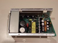
If I'm right about the circuit, then it can be configured for 115V or 230V operation depening on how the diode bridge (that four-legged thing in the left side of the heatsink) and those two big capacitors are wired.
This is a typical schematic showing 115V/230V selection. The "input filter" is inside that steel or iron box in the left side. D21, D22, D23 and D24 constitute the diode bridge. C5 and C6 are those two big capacitors. You may even find a PCB jumper for voltage selection in place of the switch shown in the schematic.
An externally hosted image should be here but it was not working when we last tested it.
This is a typical schematic showing 115V/230V selection. The "input filter" is inside that steel or iron box in the left side. D21, D22, D23 and D24 constitute the diode bridge. C5 and C6 are those two big capacitors. You may even find a PCB jumper for voltage selection in place of the switch shown in the schematic.
- Status
- This old topic is closed. If you want to reopen this topic, contact a moderator using the "Report Post" button.