Dear all,
First of all. I would like to say sorry to Pedja because my design of this KIts which use AD844 OP-amp output stage was samilar to his design. Although the working condition, selection of chips
Pedja use J-fet, I use regulator IC was different. But the circuit design is similar. After the judgement of Jean-paul( moderator). The previous thread was closed & I can not amend any informations to the 18 buys of this kits.
To prevent for any or further agruement. The C board of my PCB will not further sold to any diyers. If U like the AD844 OP-amp output stage. pls ask for pedja, But Pedja's design which compare to me had some different. He use one TDA1541a but I use Two,working in parallel condition. The Best that I can was I think My PCB was one of the Best that in DIY DAC.
For My design pls visit.
http://johnson.tmfc.net/audio/file
The AD844 Schematic was still in this file. But this is for your reference only. I WILL NOT PROVIDE ANY PCB OR SUGGESTIONS FOR AD844.
The multiple output stage for different tubes was my design.
Also, I will post my new deisgn for the RE-clock circuit in this forum first to prevent any agruement as previous THAT involve the copyright with others.
At last I would like to say that my design or kits will not assume EARN MONEY. I only hope to PROVIDE the BEST Price/cost ratio to build kits to DIYERs.
An excellent circuit need high quality parts, otherwise cannot perform its really condition.
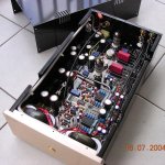
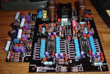
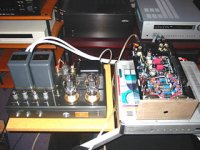
Photos shows is the previous photos about the full look of the DAC.
I still test some parts for improvement. I will continous amend it.
thanks
thomas
First of all. I would like to say sorry to Pedja because my design of this KIts which use AD844 OP-amp output stage was samilar to his design. Although the working condition, selection of chips
Pedja use J-fet, I use regulator IC was different. But the circuit design is similar. After the judgement of Jean-paul( moderator). The previous thread was closed & I can not amend any informations to the 18 buys of this kits.
To prevent for any or further agruement. The C board of my PCB will not further sold to any diyers. If U like the AD844 OP-amp output stage. pls ask for pedja, But Pedja's design which compare to me had some different. He use one TDA1541a but I use Two,working in parallel condition. The Best that I can was I think My PCB was one of the Best that in DIY DAC.
For My design pls visit.
http://johnson.tmfc.net/audio/file
The AD844 Schematic was still in this file. But this is for your reference only. I WILL NOT PROVIDE ANY PCB OR SUGGESTIONS FOR AD844.
The multiple output stage for different tubes was my design.
Also, I will post my new deisgn for the RE-clock circuit in this forum first to prevent any agruement as previous THAT involve the copyright with others.
At last I would like to say that my design or kits will not assume EARN MONEY. I only hope to PROVIDE the BEST Price/cost ratio to build kits to DIYERs.
An excellent circuit need high quality parts, otherwise cannot perform its really condition.
Photos shows is the previous photos about the full look of the DAC.
I still test some parts for improvement. I will continous amend it.
thanks
thomas
Attachments
tube-lover said:Although the working condition, selection of chips
Pedja use J-fet, I use regulator IC was different.
Hi,
That is correct. I don't know what was your first intention (IC or FET cs) but on your schematic IC 7805 is designated as Q not U what is strange.
Design with any CS and AD844 is obviously Pedja's IP on this board what is also strange to me.
One moderator’s clarification of this incident will be nice.
But who am I to ask .......
Regards
Milan
//TDA1541A PCB Already
moamp,
thanks for your comment, so I cancell the AD844 already & advise any questions directly ask to pedja.
We all are diyer, we love diy. Not like in this level or question ( similar design) cost so many agruement.
This several days I test something about my kit I would like to amend is the tube Buffer PCB's filament regular Heat sink must added large for 4 Cm Height. Unless U use the AC to small tubes.
If U use the High efficiency Speaker as AER or Lowthers.( I use Philips 9710M) U try to double the filament 6.3V to 12.6V than use diode to rectify. its ~17V than use LM317 to regulate. But it need drop ~10V. The heat sink will very hot. So change to large heat sink will more stable.
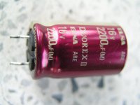
I was testing the effect of NON-polar caps which will effect on the circuit.
I was the dealer of Japan Elna caps, so I can maintain a reasonable price to resell. So it means the diyer can use this non-polar caps in very good price.
thanks
thomas
moamp,
thanks for your comment, so I cancell the AD844 already & advise any questions directly ask to pedja.
We all are diyer, we love diy. Not like in this level or question ( similar design) cost so many agruement.
This several days I test something about my kit I would like to amend is the tube Buffer PCB's filament regular Heat sink must added large for 4 Cm Height. Unless U use the AC to small tubes.
If U use the High efficiency Speaker as AER or Lowthers.( I use Philips 9710M) U try to double the filament 6.3V to 12.6V than use diode to rectify. its ~17V than use LM317 to regulate. But it need drop ~10V. The heat sink will very hot. So change to large heat sink will more stable.
I was testing the effect of NON-polar caps which will effect on the circuit.
I was the dealer of Japan Elna caps, so I can maintain a reasonable price to resell. So it means the diyer can use this non-polar caps in very good price.
thanks
thomas
Attachments
Great work Strohmie!
I received the PCB/kit already but I haven't started yet. I was surprised by the quality of the PCB and how strong it is. This black PCB is cool...
I think I will go for the 6DJ8 tube option instead of the AD844.
I am thinking about changing all 28 decoupling caps to MKP 0.47uf, any idea of upgrading??
Cheers.
The only thing I'm personally planning on upgrading is the pulse transformer, which I'll probably replace with a Lundahl LL1572 (I think the LL1566 that Thomas mentions as an upgrade is discontinued). It's much easier to upgrade one tranny than 28 caps.
Meanwhile I'm just hoping I didn't fry the CS8414 while installing it -- my Rat Shack soldering iron wasn't exactly specifically designed for such things.
I accidentally crushed one of the SMD caps, so that definitely needs to be replaced too. Thomas was kind enough to send two extras with my kit, but my mother was kind enough to vacuum them up after knocking them off my table.
Back to work.
I am still waiting for my kit, meanwhile I have been looking at the AMVECO transformers. I am having trouble finding a 210-0-210 transformer for the tube stage, lots of single secondary 210 VAC, but dual, no luck yet. Any ideas other than running two transformers and tieing them together?
Regards
Anthony
Regards
Anthony
up and running
Got my kit running last night, pretty much without issue. I have used the AD844, as I'm down a few pieces to complete my intended o/p stage, which is the 6c45pi se config.
I think the 844's sound a bit electronic, particularly compared to my Sowter 8347 transformers, which I have on my own prototype board, but there hasn't been any burn in as yet. Great bass integrity though, however the image is a little recessed.
I must say I agree that the pcb quality is excellent, one of the best I've ever seen, and will be robust enough to allow tweaking on a grand scale.
Incidentally, there is a small labelling error on the TDA1541A board, which will cause a problem if you, like me, want to use I2S.
pin 1 says data, it should be on pin 5
pin 3 says Serial clock, and it is correct
pin 5 says Syn, and it should be on pin 1
I think the schematic is right, it's just the screen printing.
My experience of soldering the 8414 was a litle nerve jangling, even with a super fine tip- fortunately, it's a pretty robust chip...keep some desoldering wick close by!
//TDA1541A PCB Already
dear Tim & Strohmie,
I was very happy to hear that U all satify the PCB.
Actually I paid more effort about this.
There was a small amend about the kit.
1. the tube buffer need a little re-work.
pls check my website or
dual_tda1541a_dac_tube_buffer_board_reworks_1.png
dual_tda1541a_dac_tube_buffer_board_reworks_2.png
dual_tda1541a_dac_tube_buffer_board_reworks_3.png
dual_tda1541a_dac_tube_buffer_board_reworks_4.png
2. If U feel that the buffer board use 6.3V filament is OK than not need to use this modify.
If U use high efficiency speaker.>96db.
may be U will like to double up the filament Than use 317/337 to regulate. 6.3V double to 12.6V than rectify will approx 20C DC.
Than pass to 317/337 to regulate to 6.3V will drop approx 14~15V the heatsink look will not enough.
If U double the voltage, I suggest use large heatsink.
3. Try LT1033 & 1085.
these chips alll can pass 3A current, lower internal resistance & lower noise.
Will much better than 317/337(1.5A only).
4. I was design the re-clock which use TCXO (temperature
compensated Oscillator" 20ppmos. The Best I can get is this one in reasonable from japan.
Anyone can help me that use 74XXXXX will better with this chips??????
I prepare call the factory to buils this re-clock which use a small copper Box to fit for it. Ground the box will lower the noise.
ANY IDEA for the chips.
thanks
thomas
Coulomb said:I am still waiting for my kit, meanwhile I have been looking at the AMVECO transformers. I am having trouble finding a 210-0-210 transformer for the tube stage, lots of single secondary 210 VAC, but dual, no luck yet. Any ideas other than running two transformers and tieing them together?
Regards
Anthony
Thomas any suggestions on my Transformer question?
Regards
Anthony
//TDA1541A PCB Already
dear anthony,
do U collect the kits already?
I change the post office which use the tracking & email to him already.
They answer me was the parcel was on canada already.
Now is on canada's custom.
I think U will collect it today. I will compliant to post office hong kong because I was post By EMS. The new zealand was collect already & canada cost much more time. This is not EMS service!!!!
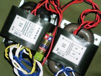
For my point. I suggest 250~0~250.
But your power transformer 210~0~210.
There may be some resisters need change.
pls give me one day. I need to test.
pls see the winding that I suggest in my power transformer.
thanks
thomas
dear anthony,
do U collect the kits already?
I change the post office which use the tracking & email to him already.
They answer me was the parcel was on canada already.
Now is on canada's custom.
I think U will collect it today. I will compliant to post office hong kong because I was post By EMS. The new zealand was collect already & canada cost much more time. This is not EMS service!!!!
For my point. I suggest 250~0~250.
But your power transformer 210~0~210.
There may be some resisters need change.
pls give me one day. I need to test.
pls see the winding that I suggest in my power transformer.
thanks
thomas
Attachments
Re: //TDA1541A PCB Already
Hello Thomas, today is Sunday here and tomorrow is a Holiday. I will likely not get my parcel until Tuesday or Wednesday.
Regards
Anthony
tube-lover said:dear anthony,
do U collect the kits already?
I change the post office which use the tracking & email to him already.
They answer me was the parcel was on canada already.
Now is on canada's custom.
I think U will collect it today. I will compliant to post office hong kong because I was post By EMS. The new zealand was collect already & canada cost much more time. This is not EMS service!!!!
For my point. I suggest 250~0~250.
But your power transformer 210~0~210.
There may be some resisters need change.
pls give me one day. I need to test.
pls see the winding that I suggest in my power transformer.
thanks
thomas
Hello Thomas, today is Sunday here and tomorrow is a Holiday. I will likely not get my parcel until Tuesday or Wednesday.
Regards
Anthony
//TDA1541A PCB Already
For dear Tim pattinson,
For your questions, pls study.
No need rework in 6c45pi pin. Only 6x4 & 6dj8.
Voltage doubler is ok, but double confirm the filament
volt is 6.3V after plug in the tubes. (two dummy
testing pads provided to measure filament voltage).
Buffer gain is not so high since we've using
2xTDA1541A,and the total gain should be ok for normal
use.
For dear Anthony,
About your questions, pls check email.
thanks
thomas
//TDA1541A PCB Already
Dear all,
small modification for my kit for update.
Some Old CD machine had this problem.
If cannot lock the CD drive, pls make below
changes,
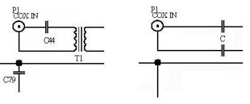
(1)Remove DAC trasformer T1
(2)Add 2x0u1 cap to T1
(3) short C79
(4) short C44
Second is special for Hong Kong DIYers.
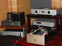
If U like to hear my DAC.
pls go to
Wing Ming Audio & Video Centre. ( This Company was Airtight tube amp in Hong Kong)
G/F, NO.77 Sai Yee St.
Mong Kok, Kowloon.
Pls directly upstair to to the the upper floor( show Room) to
hear combine with Airtight ATM-1,ATM-300(300B SE)& flatship 211SE.
call them inform shop manager Eric Sit
I hope can received more advise of my DAC to get improvement.
thanks
thomas
Dear all,
small modification for my kit for update.
Some Old CD machine had this problem.
If cannot lock the CD drive, pls make below
changes,
(1)Remove DAC trasformer T1
(2)Add 2x0u1 cap to T1
(3) short C79
(4) short C44
Second is special for Hong Kong DIYers.
If U like to hear my DAC.
pls go to
Wing Ming Audio & Video Centre. ( This Company was Airtight tube amp in Hong Kong)
G/F, NO.77 Sai Yee St.
Mong Kok, Kowloon.
Pls directly upstair to to the the upper floor( show Room) to
hear combine with Airtight ATM-1,ATM-300(300B SE)& flatship 211SE.
call them inform shop manager Eric Sit
I hope can received more advise of my DAC to get improvement.
thanks
thomas
Attachments
Re: //TDA1541A PCB Already
Is this what you mean? (see attachment)
tube-lover said:(1)Remove DAC trasformer T1
(2)Add 2x0u1 cap to T1
(3) short C79
(4) short C44
Is this what you mean? (see attachment)
Attachments
//TDA1541A PCB Already
hi Strohmie,
U right. But this is only for some of the CD drive.
If your CD drive can log by the DAC, forget about it.
For Hong Kong Diyer, if U like to hear the performance of my standard kit.
pls go to-------
Wing Ming Audio & Video Centre.
G/F, NO.77 Sai Yee St.
Mong Kok, Kowloon.
Pls call them directly upstair to to the the upper floor( show Room) to
hear combine with Airtightm ATM-1,ATM-300(300B SE)& flatship 211SE.
call them inform shop manager Eric Sit that U are thomas friend is OK.
thanks
thomas
Attachments
Re: //TDA1541A PCB Already
Cool!
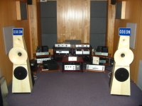
tube-lover said:HI all,
now my DAC was testing with this amp & speakers.
thanks
thomas
Cool!
//TDA1541A PCB Already
Dear nl,
thanks for your comment.
I need amend some of the data which missing in the construction menu.
For thr tube PCB Board.
Pls see the reference voltage,
(1) Using 6C45
Voltage across C5=270V
Voltage across C3 or C43=210V
Voltage across 6C45 plate to GND (pin7 & GND)=80V
(2)Using 6DJ8
Voltage across C5=270V
Voltage across C3 or C43=200V
thanks
thomas
- Status
- This old topic is closed. If you want to reopen this topic, contact a moderator using the "Report Post" button.