I'm not Peter but...
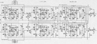
Its just an opamp I/V, opamp LPF and opamp output stage. It looks complex because it is built discrete ( HDAM ) and balanced. Compare it to a cdplayer with normal opamps and you'll notice it is almost the same except for the balanced design which doubles everything. In a Denon with balanced outputs there are 3 dual opamps per channel doing the same job ( with more circuitry internally but with much smaller footprint ).
I expected a nicer I/V to be honest.
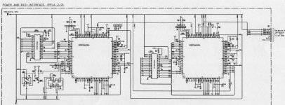
The Left and Right channels are separated, so it's not vanilla IIS but maybe some sony format.
What I don't understand is how they get one chip to output L+ L- (or R+ R-) , especially with the DAC configured for IIS input
You'll also notice that even here, BCK is connected to SCK. And even more: pin 4 is reffered as SCK, on this player designed for a TDA1541A
Maybe some pre-processing is done in the digital filter, to send some tata when WS=0, and the 2's complement of the same data when WS=1
The FF only seem to be some synchronous reclocking or WS and Data, synchronously to BCK.
The Left and Right channels are separated, so it's not vanilla IIS but maybe some sony format
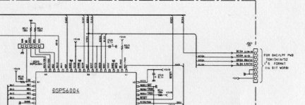
Exactly, this is not standard I2S. CD 7 does not use a standard digital filter but a specially programmed DSP.
jean-paul said:
Exactly, this is not standard I2S. CD 7 does not use a standard digital filter but a specially programmed DSP.
Ok your message confirms that I was thinking.
Instead of a classical IIS signal like this:
<WS=0> left data bits <WS=1> right data bits [DAC outputs analog values] <WS=0> next left input....
we have this:
-left DAC:
<WS=0> left+ data bits <WS=1> left- data bits [DAC outputs analog values] <WS=0> next left+ input....
right DAC:
<WS=0> right+ data bits <WS=1> right- data bits [DAC outputs analog values] <WS=0> next right+ input....
You need a DSP to do this

Bricolo said:The Left and Right channels are separated, so it's not vanilla IIS but maybe some sony format.
What I don't understand is how they get one chip to output L+ L- (or R+ R-) , especially with the DAC configured for IIS input
You'll also notice that even here, BCK is connected to SCK. And even more: pin 4 is reffered as SCK, on this player designed for a TDA1541A
Maybe some pre-processing is done in the digital filter, to send some tata when WS=0, and the 2's complement of the same data when WS=1
The FF only seem to be some synchronous reclocking or WS and Data, synchronously to BCK.
Guys please: pin 27 is connected to 28. It IS I2S for the TDA. That it gets +left and -left, it is unaware of. It just converts whatever comes in. Sounds very familiar to me
The dig filter must be configured to split i2s and feed +l/-l and +r/-r to the dacs. There is no other way this would work.
Pin 4 is strange. SCK does not exist on A version, so it is no use to put crap onto that pin.
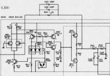
More interesting that this, is that the -5 is made from the -15 and not from a separate supply. It makes sense, if you read the post in the digital section.
gr
Peter Daniel said:
I still don't know how to split data into right and left channels.
Why not, the info is available in the digital section..
Peter Daniel said:I wasn't following that topic lately, that's why I guess
Which thread exactly? Not the one you started a year ago, or so?
It is longer than that and i did not start it. Called 2 TDA1541A in the digital section. Splitting works well.
However, thanks to HtP in the tda1541 info post, i now know that things can be done better around the 1541 (dem reclock, PS, I2S signals etc). So i'm gonna check that out with a new dac with only one 1541 first.
As for this old post: the GAL definitions can be done simpler (mentioned in other posts, seatch for 'GAL' and there is one improvement on the schematics (not tested yet):
pin 1 from the GAL (clock) should be connected to the 11MHz with an inverter to remove the jitter introduced by the '161 on BCK.
Regards,
guido said:Splitting works well.
@ the moment I would be more interested in splitting the signal into +r/+r and -r/-r.
2 chips for each channel.
My listening impressions so far:
SAA7220A + TDA1541A:
Strong odd order harmonics and suppressed even orders
Sounds

SAA7220A +TDA1541:
All harmonics distributed evenly, low distortion
Sounds detailed and clean.
SAA7220B + TDA1541(A):
Very good values for K2/K3, but dominating K5
Sounds clinical, narrow and dry.
TDA1541(A) non os:
Medium distortions, but mostly evenly distributed, suppressed K9 & tendential stronger low orders.
Sounds very open & relaxed due to rich harmonics, a little bit watered though.
jean-paul said:
Exactly, this is not standard I2S. CD 7 does not use a standard digital filter but a specially programmed DSP.
Jean-Paul, do you know if the 1541s in the CD7 are used as non-os, 4*os or 8*os?
- Status
- This old topic is closed. If you want to reopen this topic, contact a moderator using the "Report Post" button.