So, I'm nearing an end of a journey. This preamp PCB I have been holding out on selling the remainders until I had everything tested and verified good. At this point, it's dead quiet into my Lowthers and sounds amazing with my dual mono F4s. I'm ready to in good confidence move the extra parts I have.
So, what I'm offering is a mix and match from the parts below. Minimum purchase is a PCB and a set of input transformers (the board can accomodate both types) and one of the kits will include the DACT. This is to ensure I move the entire lot here.
I'm interested in trading for Semisouth parts, otherwise payment via PayPal.
I'd like
$130 for the PCB + transformer set
$280 for the PCB + transformer + attenuator set
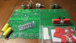
The other items in the picture are a (nearly complete) set of resistors and Wima caps I used to prototype things, a few of the depletion-mode MOSFETs needed for the circuit (no need to match, there is the ability to dial them in in-situ on the PCB), a pair of .33uF/400V Relcap RT caps that could be used for two of the four the output caps or for the PSU bypass), and lastly a stuffed and tested Maida regulator board for the PSU (which can be changed to implement the temperature compensated version of the circuit and with Darlington BJT or MOSFET pass transistor). You are encouraged to make me an offer on any of the above as well")
There are plenty of pics of my build in the Impasse Preamplifier thread. This board wil either fit the custom FPE case, or the Lansing enclosure that I used for the PSU. Everything should be readily available to complete this wonderful project.
Thanks!
So, what I'm offering is a mix and match from the parts below. Minimum purchase is a PCB and a set of input transformers (the board can accomodate both types) and one of the kits will include the DACT. This is to ensure I move the entire lot here.
I'm interested in trading for Semisouth parts, otherwise payment via PayPal.
I'd like
$130 for the PCB + transformer set
$280 for the PCB + transformer + attenuator set
The other items in the picture are a (nearly complete) set of resistors and Wima caps I used to prototype things, a few of the depletion-mode MOSFETs needed for the circuit (no need to match, there is the ability to dial them in in-situ on the PCB), a pair of .33uF/400V Relcap RT caps that could be used for two of the four the output caps or for the PSU bypass), and lastly a stuffed and tested Maida regulator board for the PSU (which can be changed to implement the temperature compensated version of the circuit and with Darlington BJT or MOSFET pass transistor). You are encouraged to make me an offer on any of the above as well
There are plenty of pics of my build in the Impasse Preamplifier thread. This board wil either fit the custom FPE case, or the Lansing enclosure that I used for the PSU. Everything should be readily available to complete this wonderful project.
Thanks!
Attachments
^ prices are firm
OK
How many components I need to complete the kit?
Wich tx are need? wich voltage & current for B+ & heaters?
You will need a transformer and a way to turn this into DC (diodes and a cap). The B+ voltage depends on how much heat sink you have on the regulator. The article recommends the following transformer:
T2 Allied 6K3VG, 650vct @ 2A Allied # 227-0005
You'll also need a way to elevate the heaters, so two resistors and a capacitor.
I'd recommend reading the thread here:
http://www.diyaudio.com/forums/pass-labs/136835-impasse-preamplifier.html
T2 Allied 6K3VG, 650vct @ 2A Allied # 227-0005
You'll also need a way to elevate the heaters, so two resistors and a capacitor.
I'd recommend reading the thread here:
http://www.diyaudio.com/forums/pass-labs/136835-impasse-preamplifier.html
Thank you, I'm still confused because can't see the B+ voltage, the voltage for heater, why the power tx is 650VCT @40DCMA, 5V@2A,6.3A@ 2.0A are you using two separate B+?, are you using 5V@2A? I'm living in Europe so I need tx with a primary of 230VAC.
I'm very interested to buy the pcb+transformer set but I need more guidance before to buy, could you help me please?
I see in the thread that depletion mosfet have to be connected in different way in the pcb or in your pcb is fixed the pcb issue?
I don't need the Maida reg I will use Salas SSHV2 for B+
I have the 0.1 & 0.47uF caps
I need two or four DN2540 depletion mosfet, how much?
Do you have 1 NE2 Neon Bulb, if yes how much for a couple?
Please give all the information you have to complete the kit, thanks in advance.
Last edited:
B+ is 350V. To determine the voltage and current for the heaters, find the tube designation on the schematic and see their respective datasheets. There is only one B+ it is using a center tapped power supply, per the schematic I linked to. I don't know anything about the SSHV2, nor its applicability to this design.
My board never had a layout issue, so there was nothing to fix.
I can add the DN2540 for $1.60 each.
I don't have any neon bulbs.
My board never had a layout issue, so there was nothing to fix.
I can add the DN2540 for $1.60 each.
I don't have any neon bulbs.
Neon bulbs are cheap and easy to get (I bought mine at Mouser, there are equivalent distributors in Europe). If it's easier, you could also connect a reverse-biased rectifier (like a 4007 type) between the grid and the cathode of the second tube. It's just there to protect the grid during power on.
- Status
- This old topic is closed. If you want to reopen this topic, contact a moderator using the "Report Post" button.