The SymAsym 5 (later 5.3) has become a sensation and people from many countries, including Poland, very quickly began to make those devices. However, the original SymAsym PCB design was faulty and many users complained about some problems with it - the common issue was an unstable operation. The PCB was also too big and looked like it was designed by someone with no experience in printed circuit board design. Despite of these disadvantages, nobody has created a better version, so I decided to do it myself.
I'm not finished yet translate the entire page but here you can read about the project in English.
http://flodins.info/sym-v2-by-flodins/82-sym-v2-by-flodins-en
I'm not finished yet translate the entire page but here you can read about the project in English.
http://flodins.info/sym-v2-by-flodins/82-sym-v2-by-flodins-en
Attachments

The SymAsym 5 (later 5.3) has become a sensation and people from many countries, including Poland, very quickly began to make those devices. However, the original SymAsym PCB design was faulty and many users complained about some problems with it - the common issue was an unstable operation. The PCB was also too big and looked like it was designed by someone with no experience in printed circuit board design. Despite of these disadvantages, nobody has created a better version, so I decided to do it myself.
I'm not finished yet translate the entire page but here you can read about the project in English.
http://flodins.info/sym-v2-by-flodins/82-sym-v2-by-flodins-en
links on your site doesn't work, were to find more infos about this ampli please?
Pricing:
9Euro/PCB
shipping to 10PCBs is 4Euro
11 to 20 is 6Euro
more than 20 is 8Euro
For now:
1EUR = 1.7USD
If someone will order more than 6 I can lower price for him.
What info do you need?
9Euro/PCB
shipping to 10PCBs is 4Euro
11 to 20 is 6Euro
more than 20 is 8Euro
For now:
1EUR = 1.7USD
If someone will order more than 6 I can lower price for him.
links on your site doesn't work, were to find more infos about this ampli please?
What info do you need?
Current euro to dollar conversion seems to be a bit better than 1.7
euro to dollar - Google Search
euro to dollar - Google Search
that didnt answer my question, is it the Symasym s 5_3?
yes, this is better version of pcb for 5.3
Mr, flodins, what is the better?yes, this is better version of pcb for 5.3

Give your place here and PCB to see the difference with the original PCB!?
thanks and cheers

Attachments
Last edited:
Please visit my website http://flodins.info/sym-v2-by-flodins/82-sym-v2-by-flodins-en
The SymAsym 5 (later 5.3) has become a sensation and people from many countries, including Poland, very quickly began to make those devices. However, the original SymAsym PCB design was faulty and many users complained about some problems with it - the common issue was an unstable operation. The PCB was also too big and looked like it was designed by someone with no experience in printed circuit board design. Despite of these disadvantages, nobody has created a better version, so I decided to do it myself.
While designing the circuit, I was doing my best to keep it being symetrical in both mechanics and currents, what has succeeded almost perfect. Moreover, I have fixed the problems with unstable operation, which were caused by too long and misplaced traces on the original PCB. The final dimensions of my design were 61x57mm.
The prototype was built in January, 2009.
A discussion about this project can be read here: http://diyaudio.pl/viewtopic.php?t=14193(some photos have expired, but you can find them on my site).
The prototype has passed tests, the board was very small and the amplifier worked stable. The sound quality was really great.
This design was appreciated by DIYaudio users, so i made a few pieces of the device for them. This version had a corrected symmetry and shortened traces of the high-impedance feedback. Effects of such changes could be only positive. I've also choosen better values for some electronic components (the whole list is published in the 'Manual' section).
Dimensions of the board were reduced to 59x58mm.
This version of the PCB was named v0.2.
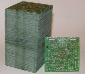
The amplifier has met so huge appreciation that DIYaudio users decided to make a group order in a PCB manufacturing company. Of course I took up to make this order and after several days they have received 150 (one houndred and fifty!) boards. The most important parameter of these PCBs was a thickness of the copper layer - it was over 105µm, which is considered to be an 'audiophile' value.
New and so far the most polished version of the PCB is now available!
The next version created to fulfill amateurs' needs.
Specification:
- the boards are joined in pairs - the joint can be cracked if needed,
- copper layer thickness 70µm,
- increased width of the supply traces, maximal current: 15A per rail,
- enlarged mounting drills, fits with M3,
- better place and lower trace length of the high-impedance feedback,
- kept placing of the output transistors, no need to change the heat sink,
- removed electrolytic capacitors from the main supply rails,
- proffesionaly manufactured - unscratchable matt silkscreen, HAL tin plating, a soldermask made in the right way (before tin plating), what makes it really resistant to any damage,
Dimensions: 60x60mm
The SymAsym 5 (later 5.3) has become a sensation and people from many countries, including Poland, very quickly began to make those devices. However, the original SymAsym PCB design was faulty and many users complained about some problems with it - the common issue was an unstable operation. The PCB was also too big and looked like it was designed by someone with no experience in printed circuit board design. Despite of these disadvantages, nobody has created a better version, so I decided to do it myself.
While designing the circuit, I was doing my best to keep it being symetrical in both mechanics and currents, what has succeeded almost perfect. Moreover, I have fixed the problems with unstable operation, which were caused by too long and misplaced traces on the original PCB. The final dimensions of my design were 61x57mm.
The prototype was built in January, 2009.
A discussion about this project can be read here: http://diyaudio.pl/viewtopic.php?t=14193(some photos have expired, but you can find them on my site).
The prototype has passed tests, the board was very small and the amplifier worked stable. The sound quality was really great.
This design was appreciated by DIYaudio users, so i made a few pieces of the device for them. This version had a corrected symmetry and shortened traces of the high-impedance feedback. Effects of such changes could be only positive. I've also choosen better values for some electronic components (the whole list is published in the 'Manual' section).
Dimensions of the board were reduced to 59x58mm.
This version of the PCB was named v0.2.
The amplifier has met so huge appreciation that DIYaudio users decided to make a group order in a PCB manufacturing company. Of course I took up to make this order and after several days they have received 150 (one houndred and fifty!) boards. The most important parameter of these PCBs was a thickness of the copper layer - it was over 105µm, which is considered to be an 'audiophile' value.
New and so far the most polished version of the PCB is now available!
The next version created to fulfill amateurs' needs.
Specification:
- the boards are joined in pairs - the joint can be cracked if needed,
- copper layer thickness 70µm,
- increased width of the supply traces, maximal current: 15A per rail,
- enlarged mounting drills, fits with M3,
- better place and lower trace length of the high-impedance feedback,
- kept placing of the output transistors, no need to change the heat sink,
- removed electrolytic capacitors from the main supply rails,
- proffesionaly manufactured - unscratchable matt silkscreen, HAL tin plating, a soldermask made in the right way (before tin plating), what makes it really resistant to any damage,
Dimensions: 60x60mm
- Status
- This old topic is closed. If you want to reopen this topic, contact a moderator using the "Report Post" button.