I've just listed this killer, custom-built folded bass horn on eBay.
I've been building bass horns for 20 years as a hobby, and this one is my best yet.
I'm selling it because we're planning a new baby and need the money. It breaks my heart because of all the horns I've built, this one is so totally rigid, clear, and true-sounding.
Imagine 145dB at 1000 Watts; I've run it that loud, and it sounds like a wrecking ball is hitting the house...I've never thought bass was TOO loud, but this thing comes awfully close.
It picks up the most subtle details; just 1 watt is sufficient for about 120dB at the mouth. Watching movies like "War of the Worlds" becomes a visceral experience. It easily puts to shame club sound systems.
This is NOT a boom-box like those bandpass boxes or a conventional ported box. Both of those color the sound horrendously.
A bass horn, on the other hand, produces extremely loud and undistorted sound because of the basic physics behind it; it is an impedance matching device, coupling the speaker cones efficiently to the air at the mouth of the horn. Effectively, with this horn, it's like having a 3 foot X 6 foot speaker diaphragm.
Because it's quite large and heavy, local pickup will be the only way to get it.
Please have a look, and message me on eBay or here if you want details.
http://cgi.ebay.com/Powerful-Bass-H...oryZ3275QQssPageNameZWDVWQQrdZ1QQcmdZViewItem
care to share with those of not within pickup distance? I'm in Ohio
care to share with those of not within pickup distance? I'm in Ohio
the picture does not serve from http://www.stuartsoftware.com/images/img_1337.jpg
Some more design details
I followed the classic exponential curve for this horn. I've had great results with Tractrix curves for horns producing >200Hz, but bass likes the tight coupling of the exponential curve.
I've found over the years that compromises in bass horn curves lead to peaky responses; they sound fine at first, but when you listen to them for a while you realize that resonances at half-octave and less are noticeable. For instance, listening to New Order's "Blue Monday", with the drum sounds pitched up and down, it sounds as though the 3rd and 4th beats are half as loud as the first two.
The "scoop bin" designs, like Cerwin Vega's DJ and club equipment, sound OK if you stack four together to give a combined mouth area that is within theoretical limits. Otherwise, the sound deteriorates to that classic Bessel curve:
| * *
| * * * * * *
| * * * * * *
| * * * * *
| * * *
| *
|_*___________________
Power-handling is a big issue if you intend to run it loudly enough that your chest is resonating and you have trouble focusing. The horn couples the drivers so efficiently in a good one that their Xmax falls way below their design spec. In this horn, at about 800W input, Xmax is about 4mm peak-peak. This deprives them of the air pumping past the voice coil through the pole vent and can cause overheating. Hence, I limit this one to 2000W peak (the driver's safe range), and 500W continuous. The drivers could do 1000W continuous but the ventilation is not adequate.
Cerwin Vega and other scoop-bins attempt to solve this with heatsinks on the back of the driver box, but it just delays the inevitable; you WILL see power compression with these tight-coupling horns. One way to solve it is by adding active cooling--some 4-inch button-fans--to the pole-vents and actively sucking air over the voice coils.
Another huge design issue is rigidity. The ultimate would be to cast the horn in solid concrete; I contemplated this as we built our house, but space and time constraints nixed the idea.
I decided instead to have a semi-movable horn--it weighs about 700 pounds, but can still be moved with the wheels on the back. To make it rigid, I used 3/4 A/A grade birch; I then filled the dead spaces between the outer box and the inner curves with A+B expanding foam. If you've ever worked with it, you know that the high-density stuff, 5lb/sq.ft., is extremely stiff when cured. In addition, during its expansion as it reacts, it produces very high pressure. I poured it incrementally, which produced enough pressure to pull out several 2-inch wood screws. I had to go back and re-do the back panel and reduce the pressure slightly.
The net result is that the whole horn is pre-stressed; the pressure of the foam is forcing the horn curve inward against the pressures it develops in operation.
If you think about it, the pressures inside a horn are significant. At 1500W, you're talking about 2 electrical horsepower. Assuming driver efficiency of 10%, it's like kicking the walls of the throat as hard as you can! Rigidity is paramount, or you risk severe coloration and power loss.
You'll notice the curved piece of plywood bracing the mouth of the horn. That piece prevents flexing of the top and bottom plates.
TESTING: I've tested this horn extensively with frequency sweeps of 20Hz-200Hz. I prefer to cross it over at about 120Hz, which is where it starts sounding directional. I haven't put a subsonic filter on it, because I designed the driver box with a small enough volume (170 liters) to resist excessive excursion at low frequency. I was very pleased that its subjective acoustics match its design so well; it works very well down to 32Hz, and falls off completely by 28Hz. "Completely" is a relative term of course, because at that point you're hearing basically a sealed-box subwoofer with two 18inch drivers! But compared to when the horn is working, it sounds quiet.
I'll gladly post HORNRESP graphs and the Excel spreadsheet I used to model it. I also wrote a C# program to model it more tightly.
I followed the classic exponential curve for this horn. I've had great results with Tractrix curves for horns producing >200Hz, but bass likes the tight coupling of the exponential curve.
I've found over the years that compromises in bass horn curves lead to peaky responses; they sound fine at first, but when you listen to them for a while you realize that resonances at half-octave and less are noticeable. For instance, listening to New Order's "Blue Monday", with the drum sounds pitched up and down, it sounds as though the 3rd and 4th beats are half as loud as the first two.
The "scoop bin" designs, like Cerwin Vega's DJ and club equipment, sound OK if you stack four together to give a combined mouth area that is within theoretical limits. Otherwise, the sound deteriorates to that classic Bessel curve:
| * *
| * * * * * *
| * * * * * *
| * * * * *
| * * *
| *
|_*___________________
Power-handling is a big issue if you intend to run it loudly enough that your chest is resonating and you have trouble focusing. The horn couples the drivers so efficiently in a good one that their Xmax falls way below their design spec. In this horn, at about 800W input, Xmax is about 4mm peak-peak. This deprives them of the air pumping past the voice coil through the pole vent and can cause overheating. Hence, I limit this one to 2000W peak (the driver's safe range), and 500W continuous. The drivers could do 1000W continuous but the ventilation is not adequate.
Cerwin Vega and other scoop-bins attempt to solve this with heatsinks on the back of the driver box, but it just delays the inevitable; you WILL see power compression with these tight-coupling horns. One way to solve it is by adding active cooling--some 4-inch button-fans--to the pole-vents and actively sucking air over the voice coils.
Another huge design issue is rigidity. The ultimate would be to cast the horn in solid concrete; I contemplated this as we built our house, but space and time constraints nixed the idea.
I decided instead to have a semi-movable horn--it weighs about 700 pounds, but can still be moved with the wheels on the back. To make it rigid, I used 3/4 A/A grade birch; I then filled the dead spaces between the outer box and the inner curves with A+B expanding foam. If you've ever worked with it, you know that the high-density stuff, 5lb/sq.ft., is extremely stiff when cured. In addition, during its expansion as it reacts, it produces very high pressure. I poured it incrementally, which produced enough pressure to pull out several 2-inch wood screws. I had to go back and re-do the back panel and reduce the pressure slightly.
The net result is that the whole horn is pre-stressed; the pressure of the foam is forcing the horn curve inward against the pressures it develops in operation.
If you think about it, the pressures inside a horn are significant. At 1500W, you're talking about 2 electrical horsepower. Assuming driver efficiency of 10%, it's like kicking the walls of the throat as hard as you can! Rigidity is paramount, or you risk severe coloration and power loss.
You'll notice the curved piece of plywood bracing the mouth of the horn. That piece prevents flexing of the top and bottom plates.
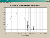
TESTING: I've tested this horn extensively with frequency sweeps of 20Hz-200Hz. I prefer to cross it over at about 120Hz, which is where it starts sounding directional. I haven't put a subsonic filter on it, because I designed the driver box with a small enough volume (170 liters) to resist excessive excursion at low frequency. I was very pleased that its subjective acoustics match its design so well; it works very well down to 32Hz, and falls off completely by 28Hz. "Completely" is a relative term of course, because at that point you're hearing basically a sealed-box subwoofer with two 18inch drivers! But compared to when the horn is working, it sounds quiet.
I'll gladly post HORNRESP graphs and the Excel spreadsheet I used to model it. I also wrote a C# program to model it more tightly.
Excel spreadsheet for modelling exponential horns
NOTE: I zipped the OpenOffice/Excel document; to view it, unzip it. The forum filters do not allow Excel files.
This spreadsheet allows you to type in Thiele-Small parameters and horn dimensions, along with "cheat factors" like half- or quarter-space loading, and arrive at actual cm-by-cm horn dimensions.
I used this during construction to plot out the curve of the horn on the bottom plate; literally, just an X-Y graph on a piece of 4X8 foot plywood.
My previous horns were flared horizontally and vertically, making this plot more complex...this horn, with parallel top and bottom, was easier to plot.
At a low crossover frequency, about 120Hz, having parallel top and bottom doesn't hurt. It also made it much more rigid; bracing a flared wall as in my previous horns was difficult.
Attachments
- Status
- This old topic is closed. If you want to reopen this topic, contact a moderator using the "Report Post" button.