Which version of circuit boards do you have? Are they built on phenolic board or fiberglass/epoxy with through plated holes. Are the little caps mylar film or ceramic?
Can you post a picture? Or, what is the serial number of your amp?
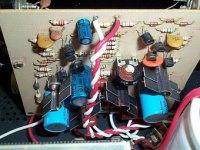
Do your circuit cards look like this one?
Would you consider selling just the circuit boards, if they are working OK?
Thanks
Can you post a picture? Or, what is the serial number of your amp?
Do your circuit cards look like this one?
Would you consider selling just the circuit boards, if they are working OK?
Thanks
Attachments
Cheaper boards like in the photo you posted. No I need to
get rid of the transformer ,caps and boards or the whole
amp. Once upon a time the amp was droped and the chassis
is warped a little so for the next 24 hours I will let the amp go
for $70 + shipping from 30290. I am posting this at 11:31 my
time so this offer expires noon 6-28-08 my time.
get rid of the transformer ,caps and boards or the whole
amp. Once upon a time the amp was droped and the chassis
is warped a little so for the next 24 hours I will let the amp go
for $70 + shipping from 30290. I am posting this at 11:31 my
time so this offer expires noon 6-28-08 my time.
")
No, it is much simpler. It was posted in The Audio Amateur by, as I recall, Walt Jung. Here is a text description:
==========
100K pot between the card's power supply rails and take its wiper, via a 2 meg resistor, to R3.
This is what Acoustat used in the TNT200 for DC Offset. A 100K Ohm, 1/4 watt variable resistor with a 2 Meg
Ohm, 1/4 watt metal film resistor should be fine, 1/2 watt would be even better, at about 4x the current capacity
you need. Place a film bypass cap across the trimmer resistor at the ±60Vdc sides to reduce AC noise from the
power supplies.
=========
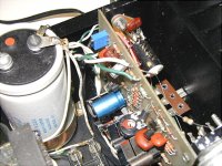
Here is a picture of it actually in use. Note the little square cermet variable resistor. I drilled several very small holes in the circuit to facilitate securing the variable resistor and wiring, then with just a touch of solder all was connected and held in place.
==========
100K pot between the card's power supply rails and take its wiper, via a 2 meg resistor, to R3.
This is what Acoustat used in the TNT200 for DC Offset. A 100K Ohm, 1/4 watt variable resistor with a 2 Meg
Ohm, 1/4 watt metal film resistor should be fine, 1/2 watt would be even better, at about 4x the current capacity
you need. Place a film bypass cap across the trimmer resistor at the ±60Vdc sides to reduce AC noise from the
power supplies.
=========
Here is a picture of it actually in use. Note the little square cermet variable resistor. I drilled several very small holes in the circuit to facilitate securing the variable resistor and wiring, then with just a touch of solder all was connected and held in place.
Attachments
- Status
- This old topic is closed. If you want to reopen this topic, contact a moderator using the "Report Post" button.