One led blinks and the other flashes with activity. The flash is so short, that It's amost invisible.
I think I must have a bad pic in the volume board (APOX 1). The board gives odd incorrect but repeatable responses to changing inputs, but not to volume adjustments. I can't wait to get a chassis built and these small glitches sorted out. This will be a fine peice of equipment. With the increasing popularity of multi channel sacds and dvda, I think I'll get 2 more APOX1 and 4 more APOX IS and make it surround ready. (Christmas present to myself maybe)
I think I must have a bad pic in the volume board (APOX 1). The board gives odd incorrect but repeatable responses to changing inputs, but not to volume adjustments. I can't wait to get a chassis built and these small glitches sorted out. This will be a fine peice of equipment. With the increasing popularity of multi channel sacds and dvda, I think I'll get 2 more APOX1 and 4 more APOX IS and make it surround ready. (Christmas present to myself maybe)
Is there are nice low voltage tube preamp that would be suitable for this? Just something simple like a 6922 or equivilent.
What I'm after, is a great sounding preamp, for not much money (after paying for metal & apox boards). Can I just copy the buffer part of the JLTi gainclone? What I was thinking was two 6922 tubes with each side paralleled per channel for a total of two tubes.
Does this sound OK?
Thanks
Gaz
What I'm after, is a great sounding preamp, for not much money (after paying for metal & apox boards). Can I just copy the buffer part of the JLTi gainclone? What I was thinking was two 6922 tubes with each side paralleled per channel for a total of two tubes.
Does this sound OK?
Thanks
Gaz
Hi Brian,
I was away for the holiday.
1) When you power up the system, the display should indicate how many boards it finds. It should indicate one input select and one volume board.
2) Since the volume increases from 0 to 255, the IR1 does see the volume board and knows that it is an APOX-1. Thus, the PIC's (on all boards) are working.
3) So, make sure that the ULN2803A chips and relays are installed correctly.
I would find it hard to believe that the PIC would communicate over I2C and not change volume correctly.
Best Regards,
Dale
Brian Donaldson said:I'm a dunce
The input select is not working, I was hearing the volume board change with the input encoder changes and assumed the input select was changing.
You can hear the relays switching on the volume board!! Wow you must hear like a bat, I thought they were competely silent!
Anthony
Hi Brian,
I assume that you have a mult-meter?
After turning on the system, measure the voltage on either IS1 board from the following pins.
The display should indicate input 1 (or its equiv)
1) IC2 Pin 10 (positive) to IC2 Pin 9 (neg)
2) IC2 Pin 1 to IC2 Pin 9
3) IC2 Pin 18 to IC2 Pin 9
4) K1 Pin 16 to IC2 Pin 9
5) K1 Pin 1 to IC2 Pin 9
Now, move to input 2 and re-measure the above
Let me know...
Dale
OK here's the #s
1) 5.01 V
2) 1.2 mV
3) 5.00 V
4) 30 mV +-
5) 30 mV +-
Same numbers +- .5% on all inputs
Also all relays trace mv between pin 1 & 16 in all input positions.
Why were you asking about voltages between 9 and 1 & 16 on K1? Pin 9 should be floating in relation to the digital power and ground. With power removed, these show > 10 megohm.
Thanks.
My moneys is on program error in the IR pic communication addresses
Hello,
It would appear that I am having the same problem as Brian Donaldson. When I power up my system, the volume select board appears to function properly, but neither of the IS1 boards are recognized by the control. The LED associated with the IS1 board does not light either.
I measured some of the voltages Dale mentioned:
1) 4.99 V
2) 0 mV
3) 5.01V
I would note that I have not yet attached the RCAs to the boards, but do not think that this should make a difference. I will double check my connections and also see if things improve if I upload the latest software.
Doh
Please post if software upgrade fixes the problem. I've always been afraid to hook any of my Frankenstien stuff up to my computer. It has all of my buisness accounting and stuff. If I crashed it, It would be a huge pain to replace and try to recover, and it wuld have to happen overnight.
Also, do you have a volume board attached? I do and my volume board reacts to input changes but not volume changes.
If your led doesn't flash, You may have a bigger problem with that board. My IR board recognizes the other boards, but doesn't make them function as they should.
Also, do you have a volume board attached? I do and my volume board reacts to input changes but not volume changes.
If your led doesn't flash, You may have a bigger problem with that board. My IR board recognizes the other boards, but doesn't make them function as they should.
On a marginally related subject, the volume encoder supplied with the APOX 2 seems to be too thin spaced, basically in maybe 1/2 turn of the knob the volume goes from 0 to max. A coarser encoder would work better here like the input selector one. The thin detented encoder should work great on the high res volume control.
The software update did not fix the problem. Here is what happens when I power the unit up:
1) Startup/splash screen. Message as follows: No input select board. Num is: 0
2) both LEDs on the volume select board flash rapidly
3) the LED on each IS1 board doe NOT flash 1x/sec per the IS1 assembly instructions
4) Turning the volume selection knob does make the relays click. LED2 on the volume select board lights briefly as I turn the knob.
5) IF the volume is set to zero, turning the input selection knob also makes LED2 on the volume select board light, though not as brightly.
6) IF the volume is non-zero, turning the input selection knob causes the relays on the volume selection board to click. (This is perhaps related to the muting which goes on when the volume is changed?)
Connecting the IS1 to IR1 directly does not seem to fix the problem. If the problem is not in the IR1, it may be that I have some sort of systematic error in assembly of the IS1 board, since neither IS1 board appears to be working. What I would like to know is what errors in assembly might cause the LED on the IS1 to not flash on power-up.
Hey everyone,
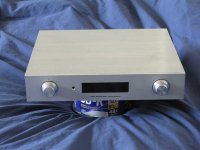
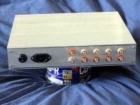
While I thought I'd post a few pics of my implemetation of the APOX kit.
The chassis dimensions are approximately 10.5 x 12 x 2.5, with front and back panels custom made by Frontpanelexpress. I found some polished aluminum plate on ebay which was the proper size. Though the pics don't show it, the sides have a mirror finish. The knobs are Kilo brand and available at Digikey.
Instead of using screws for a majority of the construction, I decided to try epoxy instead. The sides are half and inch thick, and provided ample surface area for bonding the bottom and front panels.
While I thought I'd post a few pics of my implemetation of the APOX kit.
The chassis dimensions are approximately 10.5 x 12 x 2.5, with front and back panels custom made by Frontpanelexpress. I found some polished aluminum plate on ebay which was the proper size. Though the pics don't show it, the sides have a mirror finish.
The knobs are Kilo brand and available at Digikey.Instead of using screws for a majority of the construction, I decided to try epoxy instead. The sides are half and inch thick, and provided ample surface area for bonding the bottom and front panels.
Attachments
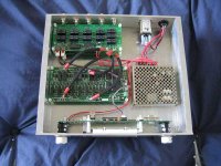
Inside, I've made attempts to keep the wiring neat. I think I may rework the power connections to make them look neater as they go from the power supply to the boards. The power supply is a 5V 3A panasonic switching power supply that I got off ebay for $10. The wiring for the signal wires was the most labor intensive. It is 21g vampire magnet wire with individual teflon sleeves. The entire bundle is then heat-shrunk with 1/4" copper braid and techflex.
I still need to figure out a way to attach the top panel to the chassis. Given how clean it looks without screws, I think I would prefer to find a way to do it seamlessly. Does anyone have any suggestions?
I still need to figure out a way to attach the top panel to the chassis. Given how clean it looks without screws, I think I would prefer to find a way to do it seamlessly. Does anyone have any suggestions?
Attachments
Hi,
Why not drill some holes into the top (not all the way though) just enough to securely plug in some small 3mm diameter rod of say 5mm in length. You should have about 4mm extruding from beneath the top cover. You then drill holes into the 4 corners of your chassis to locate these pins into.
That'll keep it quite secure and no screws visible. You could taper the pins to hold in tight if you wanted. You would need to epoxy the pins to the cover to stop them coming out.
Amazing work by the way...Extremely inspirational!
Thanks for the pics!
Gaz
I think the nicest part of this project is that it was done without the need for a lot of tools. I live in a small apartment in Manhattan, so don't have a lot of space for large tools like a drill press. All of the assembly was done with a 12" bar clamp, a power drill and bits, epoxy resin, and a set of 4-40 thread taps from mcmaster carr. Heatshinking was accomplished quite ecomomically by simply holding the cable assembly over an electric stove. All of the panels were bought cut to size, and the only panel which required finishing was the top, which was done by hand with a sanding block. I'm very pleased with how well this project came out. By far, it is the best looking thing I've ever built.
Thanks for the idea about using the rods. It sounds like a great solution. I think the hardest part about that approach would be to make the pins and holes line up properly. I have some extra bar stock that isn't quite square. I'll try drilling some holes into it to see if I can do it with enough precision.
Dale, thanks for the quick reply. I'll do some disassembly tonight and try to post the boards to you ASAP.
Hey Doh
If you want to keep with your beautiful clean look, maybe after it is all working, glue the tom on with clear silicone caulk. If you need to, you can pry it back open from the back and recaulk to reseal it.
I also like your all passive Idea.
Hey Dale
I'll send you all 4 boards because I think my problem lies in the IR. I can't believe that I messed up all 3 slave boards. There's not that much to mess up. Besides, It would be much cheaper to send all together than seperate later if there is no problem with IS boards.
I got DOH's boards today and found that they had badly programmed PICS. Why? I don't know. After re-flashing them and putting back into the boards, they worked fine.
Luckily, they were not marginal. There was no activity at all.
Guess that I should be getting Brian's system in a couple of days. Hopefully, the problem will be as simple.
Best Regards,
Dale
Luckily, they were not marginal. There was no activity at all.
Guess that I should be getting Brian's system in a couple of days. Hopefully, the problem will be as simple.
Best Regards,
Dale
- Status
- This old topic is closed. If you want to reopen this topic, contact a moderator using the "Report Post" button.