crimson 620
Hi
I have a amplifier crimson 620 (and 2 preamp 610C) and i have drawn the schématic ,but i don't be sure the value of 2 resistor output (0.22 ohms or 0.15 ohms )?
The bias measure is 0.7mV rail + and 1.7mV rail - on my amplifier , it's true ?
I have change all the capacitors and 4 diodes schottky main psu .
The listen of the amplifier is amazing, magic même a low level !!!
I have built a clown of amplifier 620 with the same component , with the same hfe (and i have drawn the pcb) .
The result listen is near the original but a little minus .
I would the reglage bias and the true value of 2 resistors output?
thanks for your answer
velfunaud
I don't know what modules were used in 620s. Some scraps of various Crimson info that may help though......
The resistors on Crimson CE1004 modules are 0R15.
The 630D amplifier used 0R22 resistors.
The 35-01 PCB use 0R18 wirewounds and have to be wirewound.
My CE1704 modules uses 10 turns of fairly thick (resistance?) wire for R27 and R28 but I've no idea of the value. It's supposed to have 15A current limiting though.
I've seen people mention 30mA bias which is what my CE1704 modules were set to if I remember correctly.
-
I don't know what modules were used in 620s. Some scraps of various Crimson info that may help though......
The resistors on Crimson CE1004 modules are 0R15.
The 630D amplifier used 0R22 resistors.
The 35-01 PCB use 0R18 wirewounds and have to be wirewound.
My CE1704 modules uses 10 turns of fairly thick (resistance?) wire for R27 and R28 but I've no idea of the value. It's supposed to have 15A current limiting though.
I've seen people mention 30mA bias which is what my CE1704 modules were set to if I remember correctly.
Thanks for your answer .I have the schématic on CE1704 would you this schématic?
Attachments
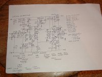
Thanks so much for that. I've been looking for the CE1704 circuit for years. It looks like the two I have in a CK1100 power amp, same output stage anyway.
Edit: I think my CE1704s may be slightly different as I haven't seen any LEDs on mine. I probably bought mine mid 80's, definitely not as late as '92.
I think there might be an error somewhere around the simulated thyristor T17 T18 section as it looks suspiciously like it would go bang with no current limiting into T15 base.
I managed to trip mine once when poking around and it shut down to a distorted sound fading to silence, requiring a power down to reset it, and has worked fine forever since.
Last edited:
- Status
- This old topic is closed. If you want to reopen this topic, contact a moderator using the "Report Post" button.