mashaffer said:Wouldn't that put your sub 180 degrees out of phase from your mains?
mike
It's non-inverting, right? Or am I missing something?
Hi,
I think this suggested circuit generally is flawed but may be somewhat useful if about 1 k Ohm resistors are inserted in series with the L and R opamps output connected to the pots.
Because if both pots are set at max and if 0 phase exist between the input signals, then max output voltage 100% is possibly only if the input amps can be paralleled without destroying each other and at this setting, the summed output depends only of input voltage tolerance.
If phase difference exists, the voltage will be lower and if 180 degrees the output voltage will be zero, thus the L and R opamps are shortening each other.
If one pot is left at max and the other is turned down, the output will still be close to 50% independent of the other pot setting but if this latter pot is turned to zero the summed voltage drops to fast to zero.
A dangerous situation will occur if one of the pots is turned max and the other pot at zero is turned up slowly, then the summed output will almost jump to 50% just by touching that latter pot.
Only if both pots are operated, the level can be balanced and set to a useful value as the pots will track each other, but is an awkward feature as the balance depends on the absolute value of L an R input signal i.e. if they are not equal the pot settings for balance is always unequal for all other possible settings.
If either pot is turned to zero, the summed output is zero or if either or both is set at max the output voltage will stay close to max and only lower to 50% if the other pot is turned down but not to zero.
I think that only one who has limited knowledge of preferred audio circuits designs prefers this type of rookie circuit.
b
Hi,
do you need independent gain of the left & right signals?
No,
then use a summing opamp (inverting) from the two inputs and then follow that with the low pass filter. This still adds up to 2opamps if you only want a 2pole filter.
If yes, then insert two buffers and a summing opamp after the gain setting pots. That adds up to 5opamps, there must be a simpler way.
I think Greg Ball posted a summer that had adjustable gain with fewer opamps but I cannot recall if the input gains were independent, or linked.
Sonusthree: " It's non-inverting, right? ..."
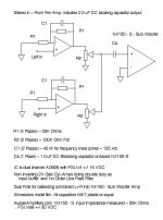
Yes, non-inverting ... Both op-amps are meant to be voltage followers.
bjorno: " ... if one of the pots is turned max and the other pot at zero is turned up slowly, then the summed output will almost jump to 50% just by touching that latter pot. ..."
... mmm, not sure here ... tis' possible under certain conditions I suppose like completely out of phase sources, L verses R, but I believe that this is what would be desirable. If Left and Right are exactly 180 degrees out of phase, then the (low passed) bass should be canceled as it would be in any case if the main stereo speakers are placed properly. This circuit is meant to exactly mimic the L and R sources with modest gain (2 X), trimmed back by the variable resistors.
AndrewT: " ... Do you need independent gain of the left & right signals? No, then use a summing opamp (inverting) from the two inputs and then follow that with the low pass filter ..."
I had hoped to keep the signal path as simple as possible with the fewest number of gain stages (reduced number of op-amps). It is a possibility that either Left or Right levels might be degraded and adjustments might be desirable. I had thought that the variable resistors (the pots) would be set once for a given pre-amp level set, then left alone. The purpose of the pots being to allow for pre-amp irregularties, rather than continuously adjustable gain ... trim pots, not volume knobs.
AndrewT: " If Yes, then insert two buffers and a summing opamp after the gain setting pots. That adds up to 5opamps, there must be a simpler way. ..."
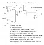
I intended the output amp, in this case the NX-150, to act as the "final" summing stage, the input of the '150 (or other) being the summing point. The 100K Ohm "trim" pots being chosen to be much larger than the 33K Ohm input impedence of the power amp.
I had hoped as well that someone would verify my calculations and configuration for the 1st order low pass filter in the op-amp negative feedback loop. I have not breadboarded this circuit as yet, but intend to as soon as I can find my op-amp chip stash.
The configuration it total will be a tube type pre-amp (ala BottleHead ForePlay) to any 10 to 100 watt chip amp or 20 to 400 watt MOSFET output amp = sub woofer / bass thumper ...
Yes, non-inverting ... Both op-amps are meant to be voltage followers.
bjorno: " ... if one of the pots is turned max and the other pot at zero is turned up slowly, then the summed output will almost jump to 50% just by touching that latter pot. ..."
... mmm, not sure here ... tis' possible under certain conditions I suppose like completely out of phase sources, L verses R, but I believe that this is what would be desirable. If Left and Right are exactly 180 degrees out of phase, then the (low passed) bass should be canceled as it would be in any case if the main stereo speakers are placed properly. This circuit is meant to exactly mimic the L and R sources with modest gain (2 X), trimmed back by the variable resistors.
AndrewT: " ... Do you need independent gain of the left & right signals? No, then use a summing opamp (inverting) from the two inputs and then follow that with the low pass filter ..."
I had hoped to keep the signal path as simple as possible with the fewest number of gain stages (reduced number of op-amps). It is a possibility that either Left or Right levels might be degraded and adjustments might be desirable. I had thought that the variable resistors (the pots) would be set once for a given pre-amp level set, then left alone. The purpose of the pots being to allow for pre-amp irregularties, rather than continuously adjustable gain ... trim pots, not volume knobs.
AndrewT: " If Yes, then insert two buffers and a summing opamp after the gain setting pots. That adds up to 5opamps, there must be a simpler way. ..."
I intended the output amp, in this case the NX-150, to act as the "final" summing stage, the input of the '150 (or other) being the summing point. The 100K Ohm "trim" pots being chosen to be much larger than the 33K Ohm input impedence of the power amp.
I had hoped as well that someone would verify my calculations and configuration for the 1st order low pass filter in the op-amp negative feedback loop. I have not breadboarded this circuit as yet, but intend to as soon as I can find my op-amp chip stash.
The configuration it total will be a tube type pre-amp (ala BottleHead ForePlay) to any 10 to 100 watt chip amp or 20 to 400 watt MOSFET output amp = sub woofer / bass thumper ...
AndrewT: " ... the NX150 in non-inverting mode cannot act as a summing amplifier. You need a summing amplifier (or opamp) to do that. ..."
Well, the theory goes like this: an amp is an op-amp is an amp ... The NX150 (and many other output gain stages = power amps) has isolated inputs, the negative (-) input is not directly connected to the local ground and likewise has an input impedence similar to the positive (+) input = 33K Ohms each, so it does have the ability to act and perform as a summing amp. ... at least that is the theory (my theory, anyway).
If an inverting stage is required for a "true" summing configuration, then you would be right ... and I would have made the initial input stage(s) inverting configuration ... but then I would have to have the next stage perform the low pass filter function as the feedback loop filter uses this. Then, you are right, there would have to be a second inverting stage ahead of the output amp to "straighten" out the phasing, a more common configuration ... (Yes, BottleHead Tube Pre-Amp into op-amp(s) =  )
)
Well, the theory goes like this: an amp is an op-amp is an amp ... The NX150 (and many other output gain stages = power amps) has isolated inputs, the negative (-) input is not directly connected to the local ground and likewise has an input impedence similar to the positive (+) input = 33K Ohms each, so it does have the ability to act and perform as a summing amp. ... at least that is the theory (my theory, anyway).
If an inverting stage is required for a "true" summing configuration, then you would be right ... and I would have made the initial input stage(s) inverting configuration ... but then I would have to have the next stage perform the low pass filter function as the feedback loop filter uses this. Then, you are right, there would have to be a second inverting stage ahead of the output amp to "straighten" out the phasing, a more common configuration
... (Yes, BottleHead Tube Pre-Amp into op-amp(s) = )Attachments
Add another inverting stage?? One would think that would put the low pass output to the sub 180 degrees out of phase with the other speakers ...?? The roll off of a second gain stage w/ 1st order filter (6 db / octive) would cause the sub woofer speaker to "cut into" or cancel some of the output from the mains, at least down in the range from 125 Htz up thru ~~ 500 Htz before the slope drop off > 20 db down ... what? ... Then there is the additional distortion component of another op-amp gain stage = I understood that each op-amp gain stage added distortion on top of distortion (on top of distortion) making the cumulative distortion beyond the usefullness of added stages of op-amps ... What?
" ... you can't just make a non-inverting input a summing point ..."
" ... are you referring to the MFB inverting filter? ... are you saying the MFB filter cannot work as a summer? ..."
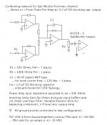
I believe that, carefully worked out, any amp can be made into a summing amp, whatever the components in the feedback loop or input configuration. Richie00boy is correct, however, that a summing network effects the feedback loop in an inverting op-amp. This is why I chose the non-inverting configuration at the beginning of this thread = several signals can be additive at the positive input without affecting the negitaive feedback ... which could include a band pass or low pass filter (actually configured as a "high pass" and in this case acting to allow a low band pass through the op-amp ... as whatever happens in the negative feedback loop is, well, negative to the band passed by the op-amp).
It has been several decades since I did any of this with op-amps, so I am not completely familiar with the MFB fliter ... please clarify ...
" ... are you referring to the MFB inverting filter? ... are you saying the MFB filter cannot work as a summer? ..."
I believe that, carefully worked out, any amp can be made into a summing amp, whatever the components in the feedback loop or input configuration. Richie00boy is correct, however, that a summing network effects the feedback loop in an inverting op-amp. This is why I chose the non-inverting configuration at the beginning of this thread = several signals can be additive at the positive input without affecting the negitaive feedback ... which could include a band pass or low pass filter (actually configured as a "high pass" and in this case acting to allow a low band pass through the op-amp ... as whatever happens in the negative feedback loop is, well, negative to the band passed by the op-amp).
It has been several decades since I did any of this with op-amps, so I am not completely familiar with the MFB fliter ... please clarify ...
It's non-inverting, right? Or am I missing something?
Oops, sorry shouldn't post so late at night. I saw the + on the bottom of the input amps and my brain ran that to ground instead of the - input that was shown on top.

mike
" ... saw the + on the bottom of the input amps and my brain ran that to ground instead of the - input that was shown on top. ..."
mmm ... I've done that more and more of late myself ... now where did I put my reading glasses ?
Seriously, having that positive input on the bottom is an old habit ... I did it as I'm used to having any feedback loop pictured on top, thus a simpler drawing to have the negative input above as well ... at least that's my excuse.
Any of these types of mistaken ID in any meatspace feedback discourse like this blog are what often results in corrections to errors later on = requiring a "re-think" of the whole circuit just to be sure ...
that is exactly why the inverting mode is used as an adder/summer.a summing network effects the feedback loop in an inverting op-amp.
The ratio of the feedback resistors sets the gain FROM EACH INPUT. Gain of channel1 input=Rfb/Rin1 and gain of channel2 input=Rfb/Rin2
The output from the inverting opamp is Vo =[V1*Rfb/Rin1+V2*Rfb/Rin2] = Rfb*[V1/Rin1 + V2/Rin2]
Now here is the bit I am guessing at.
Look at the MFB and you will see the same Rfb resistor as the global feedback from output back to the first junction point. The input resistor (Rin) is the first gain setting resistor. This part of the MFB is IDENTICAL to an inverting opamp. I know that these two resistors (Rin & Rfb) set the gain of the MFB independently of the Q & F settings. I guess that makes the first junction the virtual ground rather than the -ve input pin which in this respect makes it different from a standard inverting adder opamp. If this is correct then inserting two input resistors provides two inputs to the supposed virtual ground and the following MFB part then adds and filters in one opamp stage.
I think you will find it fruitful to plugboard this before doing any of your other layouts.
BottleHead Tube Pre-amp is apparently around 470K Ohms output impedence ~~ 11X larger than the 33K summing input resistance. ... but I would hope that the circuit would be available for alternate pre-amps as I am mixing and matching all the time, trying different combinations of pre-amps and amps. (Shortly the BottleHead will be serving duty as input switching & level control of OppoDigital.com 981 DVD-A / SACD player, old NAD digital FM tuner and BottleHead Seduction phono pre-amp, but I have plans for a DAC (a DIY project) from computer / media server and several other source devices, some tube type, some not ... )
" ... third opamp could still become a two pole MFB filter instead of just a single pole. ..."
Got a sketch ?? By MFB do you mean passive on the third op-amp output or "active" within the feedback loop?? ... ... Thanks so much
" ... third opamp could still become a two pole MFB filter instead of just a single pole. ..."
Got a sketch ?? By MFB do you mean passive on the third op-amp output or "active" within the feedback loop?? ...
... Thanks so muchNo Andrew I was saying Eddy's original circuit wouldn't work. Maybe that was too harsh. You can passive sum, but you need to add source resistance and expect some loss at the summing junction, and the possibility of interaction between the two (or more) input sources. IMO just not worth it when virtual earth summing is so much better and would only take one op-amp more.
- Status
- This old topic is closed. If you want to reopen this topic, contact a moderator using the "Report Post" button.
- Home
- Loudspeakers
- Subwoofers
- Summing Op-Amp circuit