One question, do you think the Re of the inductor should be added to Re (driver) or Rg (amp output resistance)?
Hi Djim,
If the inductor is considered to be part of the loudspeaker system, then the resistance should be added to Re so that the effect on system electrical impedance, phase, group delay and efficiency can be seen.
Speaker cable resistance on the other hand, should be included in Rg.
Kind regards,
David
Hi Oliver,When I don't forget about it I add .05 Ohm for every mH to Rg, and .1 Ohm for cable resistance. I find this method useful to see what would happen if the inductance is higher at low frequencies than the standard data sheet value.
Thanks, haven't tried that yet for an inductor. Actually, I 'm thinking of a replacement circuit (made with the wizzard perhaps) if I can find a good source that explains the effect.
Last edited:
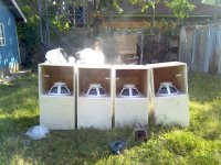
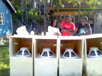
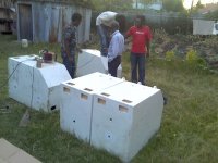
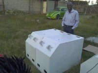
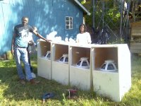
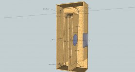
my project th118
Attachments
-
 Pic_1018_002.jpg157.8 KB · Views: 1,197
 -
 15 tapped horn with RCF tapped horn jpeg.jpg401.2 KB · Views: 616
 -
 15 tapped horn with RCF graph1.jpg106.8 KB · Views: 560
 -
 15 tapped horn with RCF 83 214983.jpg28.4 KB · Views: 1,766
 -
 Pic_1018_007.jpg151.9 KB · Views: 407
 -
 Pic_1018_027.jpg114.2 KB · Views: 358
 -
 Pic_1018_026.jpg104.1 KB · Views: 1,071
 -
 Pic_1018_003.jpg153.1 KB · Views: 1,090
 -
 Pic_1018_022.jpg136.3 KB · Views: 1,097
 -
 Pic_1018_020.jpg138.1 KB · Views: 1,123
Hi Oliver,
My worry was more about the raising of the Qes.
Qes-system = {(Ri + Re) : Re} x Qes
(Ri = Resistance inductor)
Hi Djim
I do make coils with trafo,s who have a big aircap, I can use 2,2 mm wire
for max 15 mH and 0,2 ohm, and even lower when I do twist more wires together to get even 0,05 like I do with weld trafos for invertors.
I have now one who I am draw now who need not a inductor or just a small one because of the infinity specs who are not perfect for tapped horn.
Nice TH18 I did see, be carefull with this wooden houses there.

regards
kees
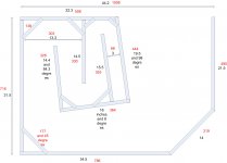
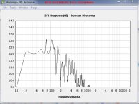
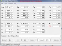
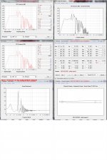
I have remake the tapped horn, now it can be used without coil but a small one do
give still a better sim, but like Djim told me it is not important because in low frequenties there are mountains.
Further it is most of the time better in real world. conus correction is done but not drawn same for reflectors in corners.
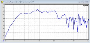
spec is within plus and min 3 dB without coil, S2 is bigger then the first one.
regards
kees
give still a better sim, but like Djim told me it is not important because in low frequenties there are mountains.
Further it is most of the time better in real world. conus correction is done but not drawn same for reflectors in corners.
spec is within plus and min 3 dB without coil, S2 is bigger then the first one.
regards
kees
Attachments
Hi All
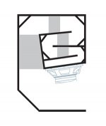
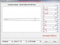
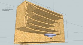
I have done a exp flare tapped horn ready for test,, it has nice delay and is 211 liters big (it is some bigger because of unused space), so smaller then a uni flare as far as I now.
The box has build up with parts in flare, I go look later to minimize that and the corners get reflectors also, without getting duct in corner smaller afcourse.
And if errors, please let me now.
regards
kees
Attachments
?????????????????????????????????
Hi All,
Has everyone left the planet......
(or information overload?)
Frans
p.s. Busy doing my PA / weekend warrior / Portable TH / what have you version. First results sucks (completely my fault), next much better (thanks to the THAM12 example, Hornresp and some members on this forum), now going for version 3, most likely a single fold 42Hz which could just about handle a band (kick and 5-string bass.) It will fit on the back seat of any car, easy to handle and corner installed. Just one will go 135 dB, flat to about 180 Hz (+/- 3 dB).
Main issue was XVAR!!!! (the models AND real world show high XMAX)
The single fold looks promising (8 mm XMAX @ 400 watts)
Sawdust, at last!
Thanks to William Cowan's encouragement and David McBean's Hornresp, and Tom Danley's all-too-rare hints (c'mon Tom, just one more hint).
Don
P.S. Check out the view, ain't San Diego great!
Don, I'm in San Diego too and have a couple of tapped horns here.
Hopefully soon I'll have my Synergy horns finished in my car too.
Also, not sure if you knew this, but there's a prosound vendor in San Diego that has SH-50s for rent. They're quite affordable; something like $40 per day.
Been reading through all the posts from page one past week or so, up to page 60 or so currently. Learnt a fair amount so far, still plenty more pages to go though ! Thought I'd post here on the off change anyone still uses the thread due to wealth of knowledgeable people on here.
I've been looking to try and design a tapped horn for home use under two JBL 8340 cinema speakers that I'm putting into square boxes to enable pole mounting. I want 20hz ideally, will be for movies, processed via a miniDSP and miniDIGI taking input from the toslink output on the TV. When I use for music, which I will undoubtedly do I aim to change HP to 35hz to make things easier on the neighbours, but the LP can be anywhere around 80-100, as the JBL's do 45hz on their own.
Am looking at a Peerless SLS-P830669 12" woofer, and it says on the data sheet that maximum linear excursion is 8.3mm, is this center-to-peak or peak-to-peak ?
I have a design in hornresp that gives me the response I want, however at 30hz exceeds 8.3mm by 2mm or so.
Can post screen shots if anyone is interested, this is all just in planning phase at the moment.
Thanks,
Myles
I've been looking to try and design a tapped horn for home use under two JBL 8340 cinema speakers that I'm putting into square boxes to enable pole mounting. I want 20hz ideally, will be for movies, processed via a miniDSP and miniDIGI taking input from the toslink output on the TV. When I use for music, which I will undoubtedly do I aim to change HP to 35hz to make things easier on the neighbours
, but the LP can be anywhere around 80-100, as the JBL's do 45hz on their own.Am looking at a Peerless SLS-P830669 12" woofer, and it says on the data sheet that maximum linear excursion is 8.3mm, is this center-to-peak or peak-to-peak ?
I have a design in hornresp that gives me the response I want, however at 30hz exceeds 8.3mm by 2mm or so.
Can post screen shots if anyone is interested, this is all just in planning phase at the moment.
Thanks,
Myles
Thanks for the reply GM, I've looked at Tymphany's Architecture Notes on their website, specifically around their SLS line and it says the spider is designed to allow more than 18mm of cone travel so that would make me think your right in them being center to peak.
Next question is on a TH that I have come up with, s2 is 800cm2 as is s3 so no expansion, with negative expansion from s3 - 34, yet response looking not bad ? -3db @ 20hz and just about plays up to 80hz which is ideal to cross over into my JBL's. Is this correct though ? Is reason why this wouldn't work ?
http://i1359.photobucket.com/albums/q791/Myles_Lewis/THSLS-P830669_zps51babdea.png
Thanks,
Myles
my project th118
Hi Stewin, nice build, what driver did you use? And how did you get rid of the ripple some commonly seen on tapped horns?
Thanks for the reply GM.....Is reason why this wouldn't work ?
You're welcome! None I can think of ATM, I mean it's a tapped, mass loaded pipe [T-MLTL], so if it meets your performance requirements at a 100 w limit.........
To better see its Xmax limits though, I recommend setting Eg = 2.83V and use the max SPL tool in the acoustic power window.
Note too that technically, L12, L23, L34 [L45] should be a parabolic expansion for typical box construction, though in your alignment the difference between the sim and reality is moot due to either being a short length or is a constant [no taper] expansion.
GM
- Home
- Loudspeakers
- Subwoofers
- Collaborative Tapped horn project