No side to side bracing - something I should have employed. Would have, too, had I not gotten frustrated with the other bracing...
Not too late, you could use 1/2" - 3/4" hardwood dowels - just drill holes on either side, push them through, twist some glue in, then use like a Japanese handsaw to trim or such.
I was wondering about T-TQWT and "port" size/excursion.
What is the max excursion for a given frequency one should have?
And what size is minimum at any given excursion?
How will a smaller opening, say 200cm2 behave at 80Hz at high output, 30mm P-P or so. (around 114dB)
And 29Hz 88mm P-P (105.9dB)
What happens if you go down to 100cm2 with a more powerful driver?
Will we hit "port compression" like ported boxes at high SPL?
Loosing 3-6dB is not uncommon and I would like to avoid that.
Bracing is probably less important in a 20Hz tapped horn than a 45Hz PA tapped horn.
For the 45Hz PA bracing was definitively required to keep it in one peace and at the same time keeping it from sounding ugly.
For LF you probably loose a little bit of output, if you even notice it.
The important part is the throat where the pressure is.
At the mouth you should be left with mostly velocity as the impedance of free air don't induce much pressure.
Just make sure that you don't get any ugly panel vibrations that are exited in the passband.
Bracing is probably less important in a 20Hz tapped horn than a 45Hz PA tapped horn.
For the 45Hz PA bracing was definitively required to keep it in one peace and at the same time keeping it from sounding ugly.
For LF you probably loose a little bit of output, if you even notice it.
The important part is the throat where the pressure is.
At the mouth you should be left with mostly velocity as the impedance of free air don't induce much pressure.
Just make sure that you don't get any ugly panel vibrations that are exited in the passband.
That's what I was thinking. I don't have my horn braced inside the throat itself, but the panels on either side of the throat are fairly well braced. I wanted to leave the throat as open as possible because the compression ratio was already about 3.25:1 and I was worried (needlessly as it turns out) about making it worse.
To be fair, that 80Hz dip is at the listening position - it could be something else in the room doing that too. It's right at the top of my intended passband, so that's why I'm so lazy about doing anything about it
")
The 50Hz and 30Hz dips are the room - had that with the old subwoofer too - IXL 18.2.2 tuned to 11Hz. I'm very pleased with the way the horn sounds so far. Also pleased I decided to put it on wheels. This thing is heavy.
Bracing is probably less important in a 20Hz tapped horn than a 45Hz PA tapped horn.
For the 45Hz PA bracing was definitively required to keep it in one peace and at the same time keeping it from sounding ugly.
For LF you probably loose a little bit of output, if you even notice it.
The important part is the throat where the pressure is.
At the mouth you should be left with mostly velocity as the impedance of free air don't induce much pressure.
Just make sure that you don't get any ugly panel vibrations that are exited in the passband.
I remember an audio textbook that explained how panel output was measured with accelerometers, and also doing something odd like buying the box in sand apart from the suspect panel and measuring output with mic.
Hi!
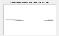
First tapped horn!?
Voice Coil of March, 2010, from page 18 on Shows article Acoustic Patents, by James Croft, and the figure 2 of a patent bellow mentioned (problably the FIRST tapped horn).
This is the patent 2,765,864 filled March 14,1955, granted Oct.09,1956, for W.E.Glenn, which describes the "tapped horn", with drawings, curves, ...
Patent Fetcher - Patent Fetcher PDF Processing
In page 20 James Croft writes:
"While all the items listed above are significant, US 2,765,864 appears to disclose the substantially SAME DEVICE that is experessed in the Danley application." ...
So TH is now public domain?
Regards,
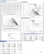
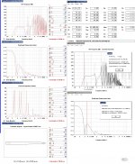
Hey all just wondering if anyone has successfully built and evaluated something like this?
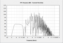
The impulse response looks a little weird but I'm assuming that has more to do with all of the eratic HF gain.
I'm not sure what this would be considered a T-TQWD? or a TH.
I don't know how well this thing would require additional HF damping above and beyond a good low pass filter. I'm sure if the speaker is over driven the resulting harmonics would be accentuated heavily.
Coupling the drive to this thing is going to be problematic. I've done a few iterations of this thing between hornresp and akabak.
But I still have to envision and model what the driver coupling to the horn/tube/whatever is and model it in akabak. Perhaps I can get akabak to predict for damping also.
I know for ducting one can change the air viscosity but I don't know if that can be applied to waveguide or if air viscosity is ~ damping (wadding).
Attachments
Last edited:
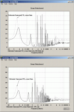
The spikes looks to be way to high in Q to be a problem in real life. I guess they should not be more then a few dB above bass region. Especially with the small opening. If at that.
Lowpass the IR in HOLMImpulse to see the real bass IR. HF garbage often shows the wrong picture.
You could probably insert a short duct every dm or so to mimic damping.
Would be hard to guess what's real though.
Or use ducts that are stepped in size. Lots of work though ether way.
You could use a front chamber to make the driver fit in the design.
BTW did any one have an answer to the vent excursion question posted earlier?
Not to bad since Hornresp exports to akabak
I can add as many wave guide segments and ducts as I want.
I am actually planning on making a coupling module (a box with an access port for the driver and taps for entering the folded 'horn'. My biggest challenge trying to subtract the rear of the driver from the volume of its enclosure, since I don't really know what that is other than from rough driver dimensions.
Not sure how to translate air viscosity into say fibreglass or poly fibre damping.
The spikes looks to be way to high in Q to be a problem in real life. I guess they should not be more then a few dB above bass region. Especially with the small opening. If at that.
Lowpass the IR in HOLMImpulse to see the real bass IR. HF garbage often shows the wrong picture.
You could probably insert a short duct every dm or so to mimic damping.
Would be hard to guess what's real though.
Or use ducts that are stepped in size. Lots of work though ether way.
You could use a front chamber to make the driver fit in the design.
I am going to spend the weekend going through this thread but is there any designs out there that can get into the teens at 110db thats about 13-15" wide?
Currently I have a THT and its pretty awesome and has made me a believer in TH designs. Problem is I have been looking at some wider speakers and the THT may have to go unfortunately.
Peters 2x12 horn looks like it may be the best bet, but the impedence is pretty low.
http://www.diyaudio.com/forums/subwoofers/160879-build-your-own-2x12-th.html
I'm working on a Shiva X2 tapped horn that sounds sort of like what you're looking for. My first try left a bit on the table, but still manages over 105 dB at the couch from 15 Hz. I've learned a bit more as a result of this build, I just need to get out in the shop and make some sawdust....
I am going to spend the weekend going through this thread but is there any designs out there that can get into the teens at 110db thats about 13-15" wide?
Mine should just barely do it at 15," but the thinnest I've modeled it is at 15" internally. That wouldn't include the thickness of the wood. In theory though it should be able to shrink down to around 13" internal width as long as the woofers like the resulting compression ratio.
The final product turned out to be 17" wide on the dot. That's with a 15.5" internal horn width and 3/4" plywood, 3.25:1 compression ratio. The woofers are handling that fine, but it's hard to say how much more compression they'd be able to stand. In its current corner placement, the hardest I've pushed it for movies is 114dB at listening position and mid 120's at the mouth. It has some gas left in the tank at that level, but not a lot. Takes about 200W at 8 ohms to do that.
You're probably better off waiting for littlemike's Shiva horn - that one should be pretty sweet. And a lot smaller than one of mine would be.
The THT isn't a tapped horn, BTW - it's a more conventional front loaded folded horn.
Edit - just modeled it with a 13.5" internal width. Response is flatter, but compression ratio is 3.73:1. That makes me a little bit nervous. Output is still well over 110dB in half space though.
Last edited:
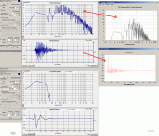
Hey all just wondering if anyone has successfully built and evaluated something like this?
The impulse response looks a little weird but I'm assuming that has more to do with all of the eratic HF gain.
Hi sumsound,
I have built a similar enclosure using a very stiff aluminium coned driver.
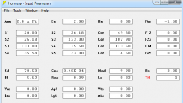
Normally muffler look-alike enclosures (exhaust silencers) are a more acoustically lossy than Straight T-QWP: s, T-TQWT’s or TH: s so if possible I recommend you to try one of those instead. See picture # 1,2,3.
You're right,
the HR impulse response is IMO less usable if not further processed. You should also stuff this ‘muffler design' enclosure like a TL or T-TQWT and of course use a LP filter when setting the upper BW boundary when integrating your main speakers.
This operation changes the impulse response of the sub if, measured separately, to something quite different but the resulting impulse response would be interpretable: See picture # 4 for an example.
b
Attachments
general design parameters of TH please
Know St is one half of Sd but is there a general tapped horn expansion rate based on freq. For example use the normal exponential expansion rate plus one third more for the specific freq in a tapped horn is that close? For example if 24 inches doubles in expo horn then 32 inches in similar freq TH. Help anyone!!
Know St is one half of Sd but is there a general tapped horn expansion rate based on freq. For example use the normal exponential expansion rate plus one third more for the specific freq in a tapped horn is that close? For example if 24 inches doubles in expo horn then 32 inches in similar freq TH. Help anyone!!
- Home
- Loudspeakers
- Subwoofers
- Collaborative Tapped horn project