Hi Don,
This is the posting you are looking for:
http://www.diyaudio.com/forums/showthread.php?postid=1777991#post1777991
b
This is the posting you are looking for:
http://www.diyaudio.com/forums/showthread.php?postid=1777991#post1777991
b
Posts #3032 / 3044
Hi Jean-Michel,
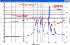
The dimensions of your tapped horn look fine. Looking again at the impedance measurement you posted in Post #3044, all the peaks are at the correct frequencies, and the general shape corresponds to the Hornresp model; but the first peak is way too small, and the second is too big. You may want to double check your amplifer output, i.e.: measure the speaker drive voltage v. frequency. The split in the third peak - right at 100Hz - looks like an airleak somewhere, maybe into the litte chamber at the end of the horn throat, or at the driver gasket?
Regards,
Hi Jean-Michel,
The dimensions of your tapped horn look fine. Looking again at the impedance measurement you posted in Post #3044, all the peaks are at the correct frequencies, and the general shape corresponds to the Hornresp model; but the first peak is way too small, and the second is too big. You may want to double check your amplifer output, i.e.: measure the speaker drive voltage v. frequency. The split in the third peak - right at 100Hz - looks like an airleak somewhere, maybe into the litte chamber at the end of the horn throat, or at the driver gasket?
Regards,
Attachments
Sneak Peak
Well, my tapped horn prototype is kind of done. It's still clamped on the glue table drying, but I couldn't reisist. I dragged the whole glueing table to the open garage size door and pointed it outside, and I went outside and measured from about 1m away.
The signal was low (I didn't want to blow out my wet glue joints), this is obviously not a measurement that carries much weight. If it's warm out tomorrow I'll do 10m measurements outside (on grass).
Keep in mind I'm using my laptop soundcard and built in mic for these uncalibrated measurements, but I find them surprisingly accurate at measuring previous projects. I zoomed in on the frequency area of interest for your viewing pleasure. No smoothing, no electronic filters of any kind applied to this measurement.
So here's a preview, measured 3 times as always, just to make sure. Details to come.
An externally hosted image should be here but it was not working when we last tested it.
Post #3124
Hi just_a_guy,
Good to see you finally got around to building (gives me hope") ), for a first test under the conditions you are describing, this is quite impressive. Is this with the TangBand W6-1139, single or dual, dimensions? It would be great if you could share some of your design data.
), for a first test under the conditions you are describing, this is quite impressive. Is this with the TangBand W6-1139, single or dual, dimensions? It would be great if you could share some of your design data.
Regards,
Hi just_a_guy,
Good to see you finally got around to building (gives me hope
), for a first test under the conditions you are describing, this is quite impressive. Is this with the TangBand W6-1139, single or dual, dimensions? It would be great if you could share some of your design data.Regards,
Post #3104
Hi Don,
I fully agree with your remarks as to the nature of the individual segments, and you are right, the single fold, uniform taper tapped horn is quite easy and quick to design, and lay out. And thanks to this thread, Tom Danley's occasional hint, and especially David McBean's Hornresp it is even accessible to dummies like me.
In Post #3102 I just wanted to point out, that I really like the Ian inspired 4-section TH model for its flexibility, and the increased possibilities for a quick exploration of different layouts without having to go all the way over to AkAbak. Even the single fold TH designs can be explored more in depth when the L23 section is split in two. I also agree with iand's Post #3101: "...Each section of the TH now only has a relatively small expansion ratio (usually 2:1 or less), and the difference between parabolic/linear/conical profiles is then negligible...".
I definitely didn't mean any offense to your designs in my Post #3102, on the contrary, I have learned a lot from your writings and contributions to this forum, so: Thank you.
Regards,
carpenter said:Cool!
What's you cutoff? Can anything be done about the 10db dip at 30hz?
Impressive!
Cutoff? I guess that depends on how you look at it... The fundamental harmonic looks to be at 23 hz or so (a bit lower than planned), but on the other hand, in marketing terms it's 17 - 160 hz (+/- 7db - but don't mention this last part in the marketing dept).
The 10db dip at 30hz? First of all, the measurements are terribly flawed in execution and really don't mean anything yet. Having said that, I think that dip is real but may not be as bad as it looks. Wait for the real 2pi measurements. At this point I'm more worried that it's overstuffed and tuned a bit too low, but again, real 2pi measurements will tell.
Good to see you finally got around to building (gives me hope
"Finally" is a relative term I suppose. IMO I used the (considerable) time very wisely, and believe me, this project was a full time job and then some for over a month and probably could have benefitted from a bit more studying. I learned a tremendous amount. Of course half that time was spent trying to learn to measure t/s specs ~ accurately, but still. I am incredibly glad I did not jump in right away and build the first ruler flat 30 - 80 hz tapped horn (with massive dual spikes up top) that I modelled. PLEASE disregard any proposed designs from me up to this point.
This design is a single tang band w6-1139si. External dims are approximately (just guessing here - I don't have the cad drawing) 9.25 x 15.5 x 44 inches.
I'm probably going to do a bit of a write up on the project when it's complete (set of 4 - and they may be unique, aka evolution in process - which could take quite awhile) but until then all I'm planning on bringing up is the cad drawing I used as plans (when I get it) and a decent 2pi measurement. So I'll try to answer any specific questions if I can, but this is nowhere near done yet.
jbell said:David: any possibility of getting a parabolic expansion added to hornresp?
http://www.diyaudio.com/forums/showthread.php?postid=1605620#post1605620
Hi jbell,
Highly unlikely at this stage, I’m afraid
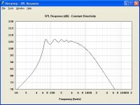
.In a conventional folded bass horn the dimensions of each segment are usually small compared to a wavelength, so that using either a parabolic or a conical expansion for an individual segment is unlikely to make much of a difference to the overall predicted system response. The important thing is to ensure that the segments, when combined, approximate the desired average flare for the bass horn (usually exponential or hyperbolic-exponential).
To demonstrate - the attached screenprint compares the SPL response of a 50Hz exponential horn having a length of 200cm against an equivalent horn made up of four conical segments each having a length of 50cm. Apart from a very slight difference at around 320Hz (which can just be seen in the attachment), the two curves are effectively identical. Practically, the overall difference in using a parabolic flare rather than a conical flare will be similarly insignificant.
Bjørn’s comment in your link above provides further confirmation:
"Checking my test design this way, the change is so small that the difference between simulated and measured results is more likely due to differences in the acoustic length."
In the case of tapped bass horns specifically, flare rates are typically so low as to make the difference between a parabolic and a conical profile completely academic.
Kind regards,
David
Attachments
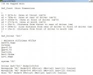
I was using a printed cad drawing as building plans and it got destroyed halfway through the build. I had the cad man email me a copy for posterity today, shown below. It's different than what I was planning in hornresp (pure conical 4 meter line), but I didn't want any wasted space, hence the odd folding which threw things out of wack so I tried to fudge my way back to the hornresp design during this cad drawing session. Basically the mouth just got bigger and it's not even close to conical anymore. The line is lined with regular pink fibreglass on 2 non parallel sides from the throat down to the driver. I figured if it needed more lining I could stuff the mouth after completion and measurements. It certainly doesn't need any more. The driver tap position is marked but you might have to look really hard to see it. Note that this drawing does not take my construction errors into account.
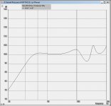
Here's some ground plane measurements taken outside today. It was quite windy and the ground is wet and mushy with spring thaw. The laptop was placed on the ground, mic facing towards the box, about 7m away (I was limited by the length of my cables). Measured 4 times, just to be sure. I guess the 30 hz dip isn't going to be a problem, but the dip at 80 hz suggests a bit of a redesign is in order. Should be easy enough to fix next time around.
An externally hosted image should be here but it was not working when we last tested it.
Bluerex said:
I would guess that it depends big time on your HT amp/processor. Mine has an option to cross-over and mix Main (L&R) with .1 (LF) or just feed the .1 LF to the sub. If you have no .1 source (2.0) you will need to mix yourself a sub channel OR use a separate crossover to extract low frequency info from the stereo feed. This could be low (line level) or speaker level (as seen in most plate amps).
Charles
==========================
Sunny Weetangera ACT
Thanks, Charles, I assume a filter like the Reckhorn units does this kind of things.
Any other suggestion ?
Re: Posts #3032 / 3044
Hi Oliver,
I use the output of the sound card "directly" to measure impedance from SpeakerWorkshop (as shown on Claudio Negro's website).
Is it wrong ? (my sound card is a Crearive SB Audigy, not sure trhe excat mlodel, but it is a low-value one).
Is there any other option ?
tb46 said:Hi Jean-Michel,
The dimensions of your tapped horn look fine. Looking again at the impedance measurement you posted in Post #3044, all the peaks are at the correct frequencies, and the general shape corresponds to the Hornresp model; but the first peak is way too small, and the second is too big. You may want to double check your amplifer output, i.e.: measure the speaker drive voltage v. frequency. The split in the third peak - right at 100Hz - looks like an airleak somewhere, maybe into the litte chamber at the end of the horn throat, or at the driver gasket?
Regards,
Hi Oliver,
I use the output of the sound card "directly" to measure impedance from SpeakerWorkshop (as shown on Claudio Negro's website).
Is it wrong ? (my sound card is a Crearive SB Audigy, not sure trhe excat mlodel, but it is a low-value one).
Is there any other option ?
Every thing else being equal!
Ah, that's the rub. If we want to compare a single taper tapped horn to a double taper
tapped horn, it would seem that we must keep all the lengths constant, S2 constant, and
the total volume constant. Why total volume? Because of Hoffman's Iron Law ...
Hoffman's Iron Law states that the efficiency of a woofer system is directly proportional
to its cabinet volume and the cube of its cutoff frequency (the lowest frequency it can
usefully reproduce). The obvious implication is that to reduce the cutoff frequency by a
factor of two, e.g. from 40 Hz to 20 Hz, while still retaining the same system efficiency,
you need to increase the enclosure volume by 2^3 = 8 times!
Will this be apples-to-apples, allowing S5 (the horn mouth) to vary? If you agree that it
will, I am willing to develop the geometry and see if the double taper has an advantage.
~Don
Post #3132
Hi Jean-Michel,
Nothing wrong with the way you measure in general, but now you are talking troubleshooting, and it would make sense to me to measure directly at the speaker driver to make sure that you are driving with equal levels at all frequencies of interest. I would even suggest (for a test) to run the amplifier output into a fixed resistor should you have one of respective value and wattage. And a separate voltmeter would not be a bad idea either.
Bye the way, if you still can get to the little chamber I suggest opening it up to the horn and seeing if you can tell a difference in the response.
Regards,
Re: Post #3070
Reticulated foam isn't cheap, but it's probably the cream of the crop for this kind of function. It's used in the waveguide of the Summas which I use, to absorb reflections from the mouth and throat.
tb46 said:Hi just_a_guy,
Walmart, fabric stores and craft store handle Poly-Fil batting, see also:
http://www.batt-mart.com/site/490194/product/BM-BY-4466
It comes in all kinds of grades. The thin open pore foam will also work.
Regards,
Reticulated foam isn't cheap, but it's probably the cream of the crop for this kind of function. It's used in the waveguide of the Summas which I use, to absorb reflections from the mouth and throat.
just a guy said:This design is a single tang band w6-1139si. External dims are approximately (just guessing here - I don't have the cad drawing) 9.25 x 15.5 x 44 inches.
I'm probably going to do a bit of a write up on the project when it's complete (set of 4 - and they may be unique, aka evolution in process - which could take quite awhile) but until then all I'm planning on bringing up is the cad drawing I used as plans (when I get it) and a decent 2pi measurement. So I'll try to answer any specific questions if I can, but this is nowhere near done yet.
I think that designs like yours are incredibly intriguing! You're getting a six inch woofer to play down to almost 20hz - that's almost unheard of.
I'd love to see more people build tapped horns with miniature drivers, as tens and twelves are almost overkill in a TH.
- Home
- Loudspeakers
- Subwoofers
- Collaborative Tapped horn project