Re: Driver ? Post #2853
G'day Oliver
The W8-740P is the driver I was referring to.
Cheers
William Cowan
tb46 said:Hi just a guy (Post #2853),
I think aceinc (Post #2848) and cowanaudio (Post #2849) were talking about the CSS TRIO-8 8" driver, its Sd=213cm^2.
Regards,
Oliver.
G'day Oliver
The W8-740P is the driver I was referring to.
Cheers
William Cowan
just a guy said:I'm always talking about the tang band w6-1139
Justaguy, I can get that TB W6 from a dutchman
Have you showed a design...and how deep will go
The supplier talks about a DVC version too...any knowledge about that one
Only one new model on TB site, a bit different

I posted a range of designs from 14 - 30 hz tuning in the last couple of weeks (including Volvotreter's excellent 30 hz tapped horn). It will go as low as you make it go, but you give up spl potential for lf extension.
The driver in my possible designs is the w6-1139SI from partsexpress. I don't know anything about any of the other models of w6-1139.
The driver in my possible designs is the w6-1139SI from partsexpress. I don't know anything about any of the other models of w6-1139.
just a guy said:I posted a range of designs from 14 - 30 hz tuning in the last couple of weeks
(including Volvotreter's excellent 30 hz tapped horn). It will go as low as you make it go, but you give up spl potential for lf extension.
I remember now, thanks
")
Didnt realise that the W6 TB was the one used in Volvotreters TH...its BIG

btw, he use drivers W6-1139SC / W61139SG / W61139G...
Attachments
Originally posted by tinitus ...its BIG
At 45L, it's the smallest design I posted. The largest was 110L. The one I'm working on is about 51L.
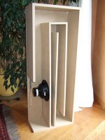
Cowanaudio Post #2861 - THSPUD
Hi William,
Thanks for the clarification, I'm having a hard time keeping track of what has been going on in the tapped horn threads. Life and work interfering with the hobby.
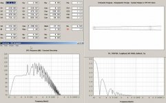
Any additional information pertaining to the use of the W8-740P in the THSPUD would be appreciated. When I model this driver in hornresp the SPL response is almost identical to the response using the MCM 55-2421, and both have quite a bit higher humps and bumps than the CSS TRIO-8 (again, modeled in the same box from Post #2821); and using mwmkravchenko's data (Post #2832) the SPL response looks even worse.
In the tapped horns for dummies thread (Post #208) Tom Danley showed a measured response, that does not correspond to my modeled hornresp response. This seems to have become a theme, anyway, a speaker that does have a SPL response in hornresp that is quite similar to Tom's measured response curve is the TangBand W6-1042J 6"x9" (modeled in a very similar box).
Anyhow, thanks for clarifying, and I agree sooner or later there has to be saw dust involved.
Regards,
Oliver.
Hi William,
Thanks for the clarification, I'm having a hard time keeping track of what has been going on in the tapped horn threads. Life and work interfering with the hobby.
Any additional information pertaining to the use of the W8-740P in the THSPUD would be appreciated. When I model this driver in hornresp the SPL response is almost identical to the response using the MCM 55-2421, and both have quite a bit higher humps and bumps than the CSS TRIO-8 (again, modeled in the same box from Post #2821); and using mwmkravchenko's data (Post #2832) the SPL response looks even worse.
In the tapped horns for dummies thread (Post #208) Tom Danley showed a measured response, that does not correspond to my modeled hornresp response. This seems to have become a theme, anyway, a speaker that does have a SPL response in hornresp that is quite similar to Tom's measured response curve is the TangBand W6-1042J 6"x9" (modeled in a very similar box).
Anyhow, thanks for clarifying, and I agree sooner or later there has to be saw dust involved.
Regards,
Oliver.
Attachments
G'day Oliver
I did the same thing and was amazed that all the response features line up perfectly (At least below 200Hz where we have data). They are lower in Q than predicted, but all the peaks and dips fall at the same frequencies. That's why I believe the W8-740P in the Spud enclosure as drawn is right on the money, or at least very close. Damping in the line could be responsible for the reduction in Q of the response features as measured.
Cheers
William Cowan
Oddly enough I have been wondering this exact thing.
My TH Mini clone is within a few DB of being the exact same. My 115 on the other hand is no where near it unless I make it just over 500 Lt. But the 115 itself has an outer size of 420 Lt. So I wonder if this could be made up by dampening ? Since clearly the Spud is lined at the driver(s).
My TH Mini clone is within a few DB of being the exact same. My 115 on the other hand is no where near it unless I make it just over 500 Lt. But the 115 itself has an outer size of 420 Lt. So I wonder if this could be made up by dampening ? Since clearly the Spud is lined at the driver(s).
I'm hoping to get a reality check on the measured parameters from anyone with experience measuring parameters. I'm pretty sure some of the parameters are good (fs, qts, qes, qms, Le), not so sure about VAS. Re measured using an ohm meter, and corresponds with the lowest spot in the impedance sweep in LIMP.

The driver was tested several times over several days, all the while being used in the small sealed box to break in.
The large difference in VAS measurement could be a big problem, not sure which to trust. VAS seems to be a factor used to calculate CMS, RMS, MMD and BL, so it would appear to be incredibly important.
Opinions? Which number should I use? An average?
just a guy said:
Opinions? Which number should I use? An average?
According to the "professors" in the art of measurements you cant trust such "home made" specs...but I really dont know

just a guy said:I'm hoping to get a reality check on the measured parameters from anyone with experience measuring parameters. I'm pretty sure some of the parameters are good (fs, qts, qes, qms, Le), not so sure about VAS. Re measured using an ohm meter, and corresponds with the lowest spot in the impedance sweep in LIMP.
The driver was tested several times over several days, all the while being used in the small sealed box to break in.
The large difference in VAS measurement could be a big problem, not sure which to trust. VAS seems to be a factor used to calculate CMS, RMS, MMD and BL, so it would appear to be incredibly important.
Opinions? Which number should I use? An average?
This stuff used to drive me up the wall. I was using Speaker Workshop to measure drivers and the specs were all over the map. I finally spent $150 on a PE woofer tester II and never looked back. Best $150 I ever spent. I like it so much I even bought a 2nd one when I couldn't figure out where I put the first one! (It's very small, the size of a keychain, and easy to mis-place.)
Patrick Bateman said:
I finally spent $150 on a PE woofer tester II and never looked back.
Just looked...100USD incl pocket scale
But I honestly dont understand why such a cheap thing would be more reliable than factory specs
Ok, I know drivers vary
But if its that significant there seems to be no point in it anyway
I mean, who wants a right and left speaker with different size

Well, I don't want to buy the woofer tester unless the results are disasterous and I absolutely need to.
I took ALL the results of the individual parameter tests and plugged them into the box design I've been working on for the factory specs. All the closed box parameter tests still look ok in the original design (these closed box parameters suggest the box is a bit too big). All the added mass parameter tests don't look quite so good (these added mass parameters suggest the box is a bit too small). So the original design looks like a good middle of the road compromise which should work reasonably well regardless of which parameters are right. But hopefully the added mass parameters are wrong, they look the worst, and the worst of those would be disaster.
So I just have to take the hornresp data, fold it up, CAD it out to get the angles and make a cut plan, build a prototype, and I should have frequency response measurements within maybe a couple of weeks. Once I get those measurements I should have a reasonable idea of which parameters were right and I can make my set of 4.
Try this Link
Just a guy
http://home1.stofanet.dk/cfuttrup/dpc.htm
This program will help you sort things out. It is a bit sparse on the interface but there is a lot that can be learned from it. Input the specs that are certain and it will figure out the rest. There are great tutorials on measurement as well in the readme files.
The Qms is linked to the total mechanical system. That is the cone, spider and surround + cone and dust cap. This measurement is effected also when you do a closed box test. If the box leaks or the seal between the box and the driver leaks you will get wild fluctuations in the measurement. It is very critical to make sure there are absolutely no leaks when you are calculating VAS.
Your specs look good except the VAS The mass added method looks close. It is also critical that you have an accurate idea of how much mass you put on the cone and if the mass is evenly distributed.
If you did the mass method carefully it is quite accurate. I personally tape on nickels to the cone and use them as weights. They are very tightly regulated for weight. You can find their exact weight on the net most years are 3.94 grams for Canadian nickels.
After measuring more drivers the long way then I care to remember I to turned to the little woofer tester. It is some sweet little thing and actually very accurate. Especially when you figure in the cost.
Mark
Thanks, that's a neat little program. Unfortuanately it doesn't help me at all. I don't have any missing parameters, I just need to verify VAS.
My chart has a typo. QMS is wrong for the added mass method, it's supposed to be the same as the closed box method. The chart is supposed to show that all parameters are within a very tight range except VAS.
My chart has a typo. QMS is wrong for the added mass method, it's supposed to be the same as the closed box method. The chart is supposed to show that all parameters are within a very tight range except VAS.
I'm moving along towards a finished th-spud style sub with Trio 8's. The drivers have arrived, most of the wood is cut, the layout has been drawn on three sides for nailing. I should have it ready for testing next weekend (lord willing & the creek don't rise)
Here's a question I should know the answer to but I'm not sure. When two 8 ohm drivers that have a rated power handling of 200 watts are hooked up in parallel the result is a 4 ohm load of course but what is the resultant power handling? 200 watts? 400 watts?
Also what is the current thoughts on the best way to attach the driver maintenance panel?
Paul
In Hornresp when using two drivers of the same type, what parameters need to be changed? I assume sd needs to be doubled and Re needs to be halved.
What about;
Mmd - Doubled?
Bl - Doubled?
Cms?
Rms?
Le?
Once I get all the parameters entered, how do I go about determining power handling?
Paul
What about;
Mmd - Doubled?
Bl - Doubled?
Cms?
Rms?
Le?
Once I get all the parameters entered, how do I go about determining power handling?
Paul
- Home
- Loudspeakers
- Subwoofers
- Collaborative Tapped horn project