But are the corrected #'s only for a true isobaric push pull type
where the shared chamber is closed?
Or would they stand for the SPUD loading type as well?
Makes me wonder about other
possible dual driver alignments. I could see some dual 10" and 12" possibilities for PA work.
where the shared chamber is closed?
Or would they stand for the SPUD loading type as well?
Makes me wonder about other
possible dual driver alignments. I could see some dual 10" and 12" possibilities for PA work.
FlipC said:Since I suck with Akabak can someone post a script for Tinituses fisrt pic there

Hi flipc
See post 2821 and 2823 by tb46/Oliver where he shows nice drawings of spud with both CSS TRIO8 and TB W8740
With same drivers you should be able to convert those taper lines into any other design you want
")
Heres another one
btw, those graphs of pushpull looks very promising, but I suppose they are still simulation
Attachments
FlipC said:yes but I suck at Akabak!
I think you missed it
With use of the nice layout from Oliver the conversion to another design is a "mechanical" job
Might be tricky though, to make it fit the new design
But draw it on big piece of cardboard and it should be possible
About acuracy
Well, I reckon no layout is 100% accurate
Heres another version
Attachments
Tinitus: can I ask you what you feel is the difference in having two drivers load a single section of line as in the Spud as opposed to your suggested loading scheme where the two drivers are seperated by a short length of line? Either way the two drivers couple to one another. The only difference that I can see is a slight tme delay one way Vs the other. I love your ideas and thinking in and out of the box so don't take this as a negative. I think that the closer and more intimately the drivers interact with one another the better to cancel out nonlinear distortion. Keep up the great posts. Regards Moray James.
Thank you James
To be honest I do have serious doubts about doing it the way I showed, with seperating drivers at throath
Thats why I hoped fore response like yours
I was just interested in investigating whether there were any possible options, in case it showed to have any advantage
Anyway, all my suggestions could be done without the seperating baffle at throath, just leave it out if you like
I will hereby finally rest my case of having concerns about whether drivers are stressing each other under heavy load, with possible risk of ressonant distortion
Fore one, theres a huge advantage of each woofer doing half the work
If woofers have very powerfull "motor" there should be no problem
If amps have plenty of power to control the woofer there should be no problem
And pushpull theory/simulation may actually work as intended, in real life too
The first tapped I will build is a center mono fore low SPL listening, and a single woofer of good quality should do very nice, but could very well be the spud/TRIO8, thanks to Oliver
The big ones will be in a few years, and lots of interesting things may happen untill then


OK, I have ordered a pair of Trio-8's from Meniscus Audio. They seem like nice chaps, at least they listened to me blather on without trying to get me off the phone.
They won't be here until next week sometime. Over the weekend I'll try to get making sawdust. I will build the TH-Spud based on the plans located here.
Any thoughts on whether to and what to line the labyrinth with? I was thinking the wool type stuff they use under area rugs. Unless I use screws I will only get one chance to treat the interior of the horn.
I am torn between birch ply ($49 sheet) and MDF ($23 a sheet). I'll probably go birch, cause it's lighter. My thought is to have Home Depot cut the side panels to size, and cut a second sheet into 4 - 48" x 11" and 5 - 48" x 9-9/16" strips.
I was going to draw the plans on one of the sides and use a protractor to measure the angles so that I can cut them as accurately as possible.
This is purely an academic exercise, in that I don't really have WAF acceptable place to put this. So I will build it, test it, play with it as much as possible, and then give it to an associate.
I have a large open front yard (about 350' x 200'), and if I can get some help I might try my own personal sub shoot out. I have a rythmik DS15, a couple of Titanic 10" in sealed cabinets and a 12" dayton DVC in a ported cabinet.
My thought is to run an extension cord to the middle of the yard put down a sheet of plywood, get my notebook running Room EQ Wizard, and see what each sub does. Not real scientific, but there might be some useful information gained. Unfortunately no one in the family has a desire to help with this sort of thing, but I might entice some associates to help.
Paul
G'day Paul
It would be great if someone in your area has a pair of the Tang Band drivers available for testing. This driver looks like a good bet in that box.
"Egg Shell" type foam would be fine down the line, with perhaps polyester wadding or felt used directly around the drivers. Don't block the path, this will decrease sensitivity a lot.
Thanks in advance for the effort. So few people are actually making saw dust, most are just speculating.
Cheers
William Cowan
cowanaudio said:G'day Paul
most are just speculating.
Cheers
William Cowan
The TB is 121 mm in depth
The TRIO8 is 90 mm
A big difference of 30mm might be convenient when doing pushpull
Especially when thspud seem to have a troath of about 100mm
Just speculating
No offence Cowan, just kidding
cowanaudio said:Thanks in advance for the effort. So few people are actually making saw dust, most are just speculating.
Cheers
William Cowan [/B]
Please don't be impatient sir. Haste makes waste. My measurement equipment is no more fancy than aceinc but you will have measurements from me too.
I'm still searching for answers to some of the questions I've asked, but in the meantime I'm pushing forward.
I've built a sealed box and got preliminary t/s measurements using LIMP. The results are consistant (the same every time) but don't make much sense so far and are way off manufacturer's specs. I think some of that has to do with their factory SD spec that I was using. They say 140 cm but if you calculate the cone area and 1/3 of the surround (as specified by LIMP) the actual cone area is almost 1/3 less than specified. Anyway, I'm hoping to sort this out within a day or 2, and then it's all systems go on the tapped horn.
This is the first time trying to measure driver parameters accurately, so I'm not going to rush it. Also, I don't have a heated workspace and I draw the line at -5 degrees C or thereabouts, so no estimate on completion date on the tapped horn build.
just a guy said:
so no estimate on completion date on the tapped horn build.
Its solely up to you, and you only
Driver ? Post #2853
Hi just a guy (Post #2853),
I think aceinc (Post #2848) and cowanaudio (Post #2849) were talking about the CSS TRIO-8 8" driver, its Sd=213cm^2.
If the Sd=140cm^2 you may be talking about the TangBand W6-1139SI.
It would be nice if you could include a reference as to which driver you are talking about.
Regards,
Oliver.
Re: Posts #2847 and #2852
Thanks
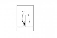
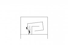
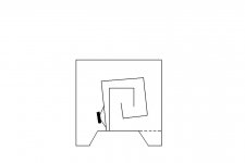
Me too...its funny, but its almost like its relaxing to look at this folding
in my files I have named it "Tapped Spiral Duo"
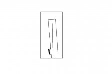
And heres the one I might do with a single SS XXLS 10"(alucone) ... I call it "Tapped Spiral Solo"
High SPL is not my goal, so with a quality driver I see no need fore pushpull
In case you missed it ... the TRIO8 in PP doesnt seem to need any special arrangements fore its magnet to fit in the throath
tb46 said:Hi tinitus,
I liked your idea in Post #2847.
Oliver.
Thanks
Me too...its funny, but its almost like its relaxing to look at this folding
in my files I have named it "Tapped Spiral Duo"
And heres the one I might do with a single SS XXLS 10"(alucone) ... I call it "Tapped Spiral Solo"
High SPL is not my goal, so with a quality driver I see no need fore pushpull
In case you missed it ... the TRIO8 in PP doesnt seem to need any special arrangements fore its magnet to fit in the throath
Attachments
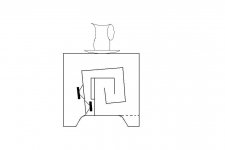
tinitus, I realize that I don't need to put in the 60 degree angle piece in order to accomadte the magnet. But, do I need the additional space, or the angle, to provide better sound?
If I don't need the angle then there I wouldn't need the side access panel, and generally it would make it a simpler build.
The actual depth is 90 mm + 5mm when the bezel is taken into consideration. Addiditonally if the wood is continued it would shrink from 100mm to about 97mm where it meets the wall. Is 3-5 mm to close for proper cooling?
Paul
aceinc said:
The actual depth is 90 mm + 5mm when the bezel is taken into consideration. Addiditonally if the wood is continued it would shrink from 100mm to about 97mm where it meets the wall. Is 3-5 mm to close for proper cooling?
Paul
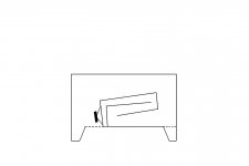
Three easy options
1. Lift the driver with additional material under chassis
2. Mount the driver as the top one, more space further up the line
3. Route away material where the magnet is located
Or combine 1. + 2.
- Home
- Loudspeakers
- Subwoofers
- Collaborative Tapped horn project