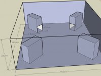
I wonder how i can determine, if i should simulate horns in 2*PI, 1*PI or 0,5*Pi. I have attached a sketch of my audio room, with intended placement of the subs. This scheme seems to be the best to supress room modes, which is why i use it. Right now, there are small closed box woofers, which i want to replace with tapped horns.
Should i simulate this setup as one horn with 4 woofers in 0,5*PI or is it better to assume the worst case which would be the response plot of a single horn in 2*PI?
The room has only one door and a very little window. Since its in a basement, two walls are of "infinite" thickness and the others are concrete.
Can someone help me with this?
Attachments
MaVo said:I wonder how i can determine, if i should simulate horns in 2*PI, 1*PI or 0,5*Pi. I have attached a sketch of my audio room, with intended placement of the subs. This scheme seems to be the best to supress room modes, which is why i use it. Right now, there are small closed box woofers, which i want to replace with tapped horns.
Should i simulate this setup as one horn with 4 woofers in 0,5*PI or is it better to assume the worst case which would be the response plot of a single horn in 2*PI?
The room has only one door and a very little window. Since its in a basement, two walls are of "infinite" thickness and the others are concrete.
Can someone help me with this?
It might be worthwhile to stack two of the tapped horns on top of each other, with the top one inverted. Then measure the response in-room.
Distributing the subs flattens the response as you know, but there's nothing to stop you from distributing them *vertically* too. Stacking them with the mouth near the ceiling accomplishes that.
Hi GM, you saw the problem ") Thanks for the hint.
Thanks for the hint.
Hi Patrick Bateman, your hint is also well reveived. Indeed this would even more smooth the frequency response, but only affect the vertical modes, between ceiling and floor. The lowest of those is in the 70s, so this isnt my first concern.
For those of interest, i can only recommend the harman papers on room response, especially the multiple sub paper.
Thanks for the hint.Hi Patrick Bateman, your hint is also well reveived. Indeed this would even more smooth the frequency response, but only affect the vertical modes, between ceiling and floor. The lowest of those is in the 70s, so this isnt my first concern.
For those of interest, i can only recommend the harman papers on room response, especially the multiple sub paper.
GM said:
Greets!
OK, true, but it's normally derived also since it's very rarely published, so still not sure why you prefer it over the ~universally used Mms.
Understood, thanks, but I was hoping you'd publish the formula. Oh well, doing a bit of Googling yielded this from Bill Geiger:
[Mmd] = [Mms]-2*([Sd]^2)*[Ma1]
[Ma1] = 8*[p0]/(3*[pi]^2*[a]) - Acoustic Mass of Air Load on one side of equivalent piston (kg/m^4)
[p0] = 1.18 kg/m^3 - Air Density
[pi] = 3.14159
[a] - Driver Effective Radiating Piston Radius (m)
[Sd] = [pi]*[a]^2 - Driver Effective Radiating Area (m^2)
GM
Hi GM,
Bill’s expression for the mechanical mass of the air load on both sides of the diaphragm of a driver mounted in an infinite baffle 2*([Sd]^2)*[Ma1] is taken from Leo Beranek’s book “Acoustics”. It is an empirical formula based on the observation of results, not one derived from fundamental theory. What the formula actually says is that the loading mass on each side of the diaphragm can be considered to be a layer of air equal in area to that of the diaphragm equivalent piston, and equal in thickness to 8/(3*pi) or ~0.85 times the piston radius. This is obviously a rather simplistic approach to take. You will notice that the approximation formula is independent of frequency. This means that the value becomes less accurate as the resonance frequency of the driver rises.
The value for Mms in Bill’s formula [Mmd] = [Mms]-2*([Sd]^2)*[Ma1] assumes that the driver is mounted in an infinite baffle. In many cases the manufacturer’s specification for Mms is actually based on an unmounted driver radiating into free space. This is often not made clear in the information provided.
Hornresp uses a more accurate and theoretically correct method by calculating the actual acoustical reactance of the air load on each side of the diaphragm, with frequency being taken into account. Without wishing to get too technical, the calculations require the use of the Struve function, the handling of which is not a trivial exercise. Unfortunately the precise result is not given by way of a single simple expression, which is why I did not include a formula in my previous post.
The reason I favour using Mmd rather than Mms is because Mmd is an absolute physical value that can be directly and very accurately measured. Mms on the other hand can only be determined indirectly. Mms values provided by driver manufacturers can sometimes be rather inaccurate, or it may be unclear whether the figure applies to a driver in an infinite baffle or to an unbaffled driver radiating into free space. Hence my preference to use Mmd where specified, or to calculate Mmd from Sd, Cms and fs (the driver free-air resonance frequency) when Mmd is not available.
Hope this helps to explain why Hornresp is the way that it is
. In principle, I try to make the results calculated by the program as accurate as possible.Kind regards,
David
Chris8sirhC said:What on earth are you using for your mains that could keep up with that setup, and which design did you end up going with?
If this question was directed at me, the answer is a pair of horns, which i designed according to tom danleys unity/synergy horns. But i dont play very loud, i just think that having lots of headroom and efficiency is a nice thing for sound quality and nerd-like satisfaction.
i see, i want to use the bms 18n600 as soon as its released, since i figured i should use the best driver i can find or else i will upgrade too soon - kinda a psychological thing i suppose. i will use four subs for room mode cancelling. i am not interested in high volumes, but in clean and effortless sound. ill build some little monitor boxes to give away from my 12 inch drivers i have right now, since they are more of a midrange than a woofer - trying to clone a summa should be fun
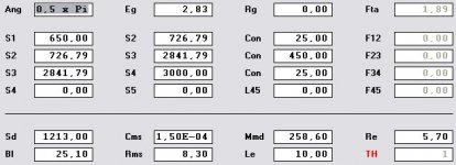
parameters are:
parameters are:
Attachments
Mavo,
how you will get bass resolution and transparenz
by low levels, (in your room below 0,01 W)with 258,6 gr mass?
as i wrote before:
The inertia of membrane mass slows the music signal, the
smaller the volume level, in living room areas usual, the
pronounced damped the moving mass of the diaphragm
signal playback, the main reason for the lack of serious bass
resolution of heavy weight bass membranes.
850 Liters and here is the driver:http://bmselektronik.de/18N860.bms_18n860_woofer.0.html will be released around end of october.
How many tapped horns have we built? With the exception of William Cowan & Volvotreter, I don't think anyone's made more than one.
I've used mine indoors, and it has overwhelmed every room it's been used in. Hope to get it outside in August, but I don't expect it to overwhelm a football field.
This is a great DIY project, and I'm surprised that so many are talking and so few are building. If you've built one, let us know!
~Don
I've used mine indoors, and it has overwhelmed every room it's been used in. Hope to get it outside in August, but I don't expect it to overwhelm a football field.
This is a great DIY project, and I'm surprised that so many are talking and so few are building. If you've built one, let us know!
~Don
Attachments
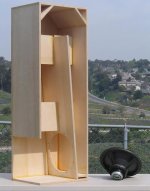
I have built two tapped horns,one straight,and one folded.The straight one is in the garage,with a hole in the wall to the listing room,and the folded one is in a closet on the other side of the room,also with a hole to feed the sound into the room.
Stereo bass is highly recommended!
400 watts into each one can really shake the room...
4 tapped horns?YIKES!!!
Here is the pic from post #210 of them before I moved them to the other side of the wall.
http://img292.imageshack.us/img292/7686/foldedhornsraighthorn00cy5.jpg
Stereo bass is highly recommended!
400 watts into each one can really shake the room...
4 tapped horns?YIKES!!!
Here is the pic from post #210 of them before I moved them to the other side of the wall.
http://img292.imageshack.us/img292/7686/foldedhornsraighthorn00cy5.jpg
- Home
- Loudspeakers
- Subwoofers
- Collaborative Tapped horn project