GM, what you said about using Leach' math for Tapped Horn design got me thinking about how applicable his whitepaper is to Tapped Horns, so I made a few AkAbak scripts to test some things. Since I have no idea how you use his Math for your designs (the only thing I could think about was for sizing the back/front chamber and choosing the driver Fs), maybe you want to play around with them?
I have tried to comment them as much as possible, so maybe you can use it as a jumpstart to learning new tri ... err ... AkAbak
Can you PM me? I have tried to send an email to you but you have it disabled.
I have tried to comment them as much as possible, so maybe you can use it as a jumpstart to learning new tri ... err ... AkAbak
Can you PM me? I have tried to send an email to you but you have it disabled.
Since i dont have any data on the drivers, i use a Peerless caraudiodriver in hornresp. It work in the previous TH i built. I know its not realy a very good idea, but i have the drivers so why not. The wood cost me about 3 dollar.
I calcualated the driver as one with the same VAS and Fs but twice the BL and SD, and four times the Mms.
The two ohms "rg" is to simulate a higher Qes and Qts.
I calcualated the driver as one with the same VAS and Fs but twice the BL and SD, and four times the Mms.
The two ohms "rg" is to simulate a higher Qes and Qts.
An externally hosted image should be here but it was not working when we last tested it.
MaVo said:Will the resonance occur at pathlength = wavelength/2 ?
jnb said:Is it worth the effort of rounding the bend and flaring the mouth (so it looks like a sax?)
I found a post from Tom Danley about this subject. Its about the Labhorn, but aplies here as well, as it seems. The part in " " is from Tom Danley.
"Picture a long wavelength, lets say it is of the highest frequency of interest, say 120 Hz.
120 Hz has a wavelength of 9.43 feet, its quarter wavelength is 28.3 inches.
When the dimensions of a chamber or passageway are less than 1/4 wave in dimension, one can treat that
space/volume/compliance as a lumped element or elements.
What that means may not be clear but here is an example of it.
Imagine a horn, that was 6 meters long, with a 28 Hz flare and a 7 sq. meter mouth area.
Instead of making a traditional horn, one made it out of pipes of stepped diameters, a "digital" horn.
How many steps do you have to have before it works like a horn, any guesses?.
Well if one made each pipe 1 meter long and did the expansion in 6 steps what would you get?
You get the exact same thing as a true exponential horn up to 150 Hz.
What you see in the radiation resistance is a small wiggling around compared to the expo BUT with the right driver, that does not show up in the acoustic output.
The effect of the steps does put a pretty deep notch in the response but the 1 meter step's first notch is at 200 Hz and the next at 400 Hz and so on. Using this box below 150 Hz, there is essentially no difference between the two.
What all this means is that when you are dealing with acoustically small dimensions, one has an extra degree of freedom
in where one puts a given air volumes etc. (like where I "hid" the front volume)
Where in a 1 inch compression driver and horn , having the rubber gasket obstructing even a tiny part of the horn throat
can kill the hf response, one can get away with a significant deviation from "the book" if its acoustic dimension is small.
Sven in folding your horns, think in terms of how big is the quarter wavelength your dealing with.
What one cannot do is significantly change the total cubic volume of the interior, air is after all this curious combination
of spring and mass and a "connectedness" to the outside.
In making a bend, a common mistake is to assume the bend is longer than it really is. Going by cubic volume alone is close but also in a bend, the air is moving in an arc and so temporarily has slightly more mass (as the bulk of the volume
is on the outer half of the radius of motion).
Also, at the frequency where the difference in path length between the inside of the bend and the outside of the bend is N 1/2 wavelengths, there are deep notches in the response.
This is a result of the opposite phases recombining (and
canceling out) after the bend. A good rule of thumb is make sharp bends with a short radius -or- bend angle is inversely proportional to radius). The point is again remember the "acoustic size" of what ever your dealing with.
As you can see on the LAB sub the only large degree bend has a small radius (the one at the nose).
Does making the fold with a radius make a difference?
Yes, it looks cool and I make them that way because something says "it should be".
I have tested a couple low frequency horns with and without and to be honest it made little or no difference.
Again what are the acoustic dimensions?
In the LAB sub, I would suggest making at least the first two bends with the radius because it "feels right" (a non technical term I admit).
Still more complication, at the point where the wall area is a significant acoustic size, the sound pressure couples to the width mode resonance (caused by the parallel walls) which puts the first in a series of notches in the response coming out of the mouth.
In this situation, there is a 1/2 wavelength standing wave with the pressure maxima at the walls and velocity max in the center.
Coupling to this mode saps off energy at frequencies related to the N 1/2 wavelengths.
Here, your horn mouth width (where it has parallel walls) also kind of sets your upper frequency limit
For a 21 inch wide horn like the LAB sub, the first width mode notch should be in the mid 300's which is a non issue."
85Hz has a wavelength of 4m, leaving the quarter wavelength at 1m.MaVo said:"Picture a long wavelength, lets say it is of the highest frequency of interest, say 120 Hz.
120 Hz has a wavelength of 9.43 feet, its quarter wavelength is 28.3 inches.
When the dimensions of a chamber or passageway are less than 1/4 wave in dimension, one can treat that
space/volume/compliance as a lumped element or elements.
What that means may not be clear but here is an example of it.
Imagine a horn, that was 6 meters long, with a 28 Hz flare and a 7 sq. meter mouth area.
Instead of making a traditional horn, one made it out of pipes of stepped diameters, a "digital" horn.
How many steps do you have to have before it works like a horn, any guesses?.
Well if one made each pipe 1 meter long and did the expansion in 6 steps what would you get?
Where does the 150Hz come from?
Cordraconis said:
GM.............
Can you PM me? I have tried to send an email to you but you have it disabled.
What's this? The 'pot calling the kettle black?'
Your PM is disabled also.Anyway, I use it for Vas, Qes and 'M' factor.
GM
AndrewT said:
85Hz has a wavelength of 4m, leaving the quarter wavelength at 1m.
Where does the 150Hz come from?
Where did you get 85 Hz/4 m?
The ~150 Hz comes from his 6 m long, 28 Hz flare frequency expo terminating into a 7^2 m mouth (At) example, though AFAIK you would have to reverse calc it's throat area (St) to find its theoretical Fh3, or St = ~105.9 cm^2 = ~944 Hz/2/pi = ~150 Hz.
GM
MaVo said:The effect of the steps does put a pretty deep notch in the response but the 1 meter step's first notch is at 200 Hz
GM said:The ~150 Hz comes from his 6 m long, 28 Hz flare frequency expo terminating into a 7^2 m mouth
Intentional coincidence? He may have designed the step related notch and the throat cutoff to be equally out of band.
200Hz does sound more like a practical 1/2 wavelength yet he did say a quarter wavelength.
The segment steps must be OK below some frequency?GM said:
What's this? The 'pot calling the kettle black?'
Anyway, I use it for Vas, Qes and 'M' factor.
GM
I checked it right before I posted that ... My PM was enabled.
Anyway, I checked it again and this time I also enabled my email adress. It should work now.
Goodnight! *yawn*
MaVo said:Well if one made each pipe 1 meter long and did the expansion in 6 steps what would you get?
AndrewT said:85Hz has a wavelength of 4m, leaving the quarter wavelength at 1m.
He asks what would you get for 1m long stepped pipes.GM said:
Where did you get 85 Hz/4 m?
85Hz has a 4m wavelength and based on the info in the Danley quote, he asks us to believe that if the quarter wavelength is longer than any physical speaker dimension it equates to the theoretically correct shape.
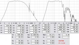
I am wondering, in which kind of implementation the tapped horn has the biggest advantage in comparison to a similar sized frontloaded horn. for example, i modeled a 40-300hz horn of both kinds, both use the same driver, have the same +-1db frequency response, the same volume, maxspl etc. here, using a TH has no benefit. can you show me cases where a TH is better (lower cutoff or more max spl or more linear response etc.) per volume than a normal frontloaded horn?
The attached picture shows both.
The attached picture shows both.
Attachments

Re: MaVo_horn comparison
This speaker was just a test, nothing i would build. I am still researching what kind of subwoofer will be the best for my listening preferences.
Yes, Danley said that, but as my example showed, the size reduction is not allways there. There have to be some paramter combinations, where the TH benefit over a normal horn is maximised and i want to know which that are.
Thats not really comparable, as i used 2 drivers and you one. But your example shows, that one is sacrificing the midbass smoothness for a smaller cabinet. Perhaps this is the direction in which the optimum performance of THs lies, as narrow bandwidth (2 octaves) low frequency transducers. The more you approach the normal frontloaded horn geometry / size, the more bandwidth you gain and the smaller is the difference between TH and normal horn.
tb46 said:Hi MaVo: I think Tom Danley pointed out, that the main benefit for the tapped horn is size reduction. Bye the way, what is the speaker you are modelling?
This speaker was just a test, nothing i would build. I am still researching what kind of subwoofer will be the best for my listening preferences.
Yes, Danley said that, but as my example showed, the size reduction is not allways there. There have to be some paramter combinations, where the TH benefit over a normal horn is maximised and i want to know which that are.
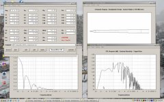
tb46 said:Here is a quick re-model.
Thats not really comparable, as i used 2 drivers and you one. But your example shows, that one is sacrificing the midbass smoothness for a smaller cabinet. Perhaps this is the direction in which the optimum performance of THs lies, as narrow bandwidth (2 octaves) low frequency transducers. The more you approach the normal frontloaded horn geometry / size, the more bandwidth you gain and the smaller is the difference between TH and normal horn.
MaVo_horn comparison
Hi MaVo: I agree it is obviously a subwoofer. Sorry for overlooking the dual drivers. Here is an example with 2 drivers, and with some more work the size can probably be decreased a little more, but this is already quite "small".
Hi MaVo: I agree it is obviously a subwoofer. Sorry for overlooking the dual drivers. Here is an example with 2 drivers, and with some more work the size can probably be decreased a little more, but this is already quite "small".
Attachments
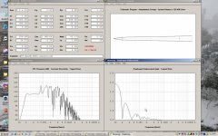
Thanks for the participation tb46, it seems - as you pointed out, that the interesting thing in THs is the ability to make the compromise of having a smaller bandwidth and getting the bonus, that a smaller volume can reproduce it with good response, all in comparison to a normal horn.
The only thing i want to get rid of, are the extreme high q peaks in the octave above the passband, to minimise the distortion of the horn, which will be to a big part, directly above the passband. So, if we achieve a TH with a falling response above its passband, it will be considerably lower in distortion.
As cowanaudio pointed out, the peaks may in reality be smaller than in simulation due to various "losses", but still, a falling response will be better.
I assume, the magic lies in choosing the right type of driver. This very high fs, high bl driver i used, has a really high cutoff, and is not practical for a TH sub. For the right driver, a high LE may help, as it lowers the R/L corner and so the upper cutoff. High mms, low fs, medium qes drivers would be probably the right choice for a lower frequency oriented small bandwidth horn. something as the lab12 perhaps?
MaVo_horn comparison
Hi MaVo: quote Post #1137: "I assume, the magic lies in choosing the right type of driver."
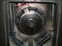
I agree. William Cowan seems to be the expert on that subject (besides Tom Danley, of course). But, it is also a systems design challenge. Yesterday I found a thread on the Klipsch Forum: "Danley Labs DTS-20 On The Way." This is a great thread pertaining to a DTS-20 installation (and major home remodelling), and contains a few internal pictures that confirm what I had assumed before, namely that Tom uses resonators and passive filtering to tame some of the major problems. Even if these big peaks can be reduced with parametric filters and a high order low pass, it still makes a lot of sense to do what you can do relatively easily right at the speaker level. It might also make the integration with the main speaker system easier.
Hi MaVo: quote Post #1137: "I assume, the magic lies in choosing the right type of driver."
I agree. William Cowan seems to be the expert on that subject (besides Tom Danley, of course). But, it is also a systems design challenge. Yesterday I found a thread on the Klipsch Forum: "Danley Labs DTS-20 On The Way." This is a great thread pertaining to a DTS-20 installation (and major home remodelling), and contains a few internal pictures that confirm what I had assumed before, namely that Tom uses resonators and passive filtering to tame some of the major problems. Even if these big peaks can be reduced with parametric filters and a high order low pass, it still makes a lot of sense to do what you can do relatively easily right at the speaker level. It might also make the integration with the main speaker system easier.
G'day MaVo
They are resonators tuned to the same frequency as the first few response peaks. You'd probably find that each branch is 1/4 WL of each peak in question. The ~5mH series inductor flattens the response and removes some of the higher frequency stuff (It's DCR doesn't hurt in many cases, too).
Cheers
William Cowan
- Home
- Loudspeakers
- Subwoofers
- Collaborative Tapped horn project